EasyManua.ls Logo

Sony TC-WE605S Service Manual

Sony TC-WE605S
44 pages
To Next Page IconTo Next Page
Page #1 background imageLoading...
Page #1 background image
TC-WE835S
US Model
AEP Model
UK Model
SERVICE MANUAL
MICROFILM
Sony Corporation
Home A&V Products Company
STEREO CASSETTE DECK
99C001668-1
Printed in Japan ©1999.3
Published by Quality Assurance Dept.
(Shinagawa)
TC-WE835S is similar to the earlier TC-WE825S.
Refer to TC-WE625/WE725/WE825S service manual (9-922-795-xx)
for information not contained in this service manual.
Items marked "*" are not stocked since they are
seldom required for routine service.
Some delay should be anticipated when ordering
these items.
Part No. Description Remark
***EXPLODED VIEWS***
38 1 * 3-021-243-01 PANEL, BACK (AEP)
1 * 3-021-243-11 PANEL, BACK (UK)
1 * 3-021-243-31 PANEL, BACK (US)
40 101 X-3374-864-1 LID (A) ASSY, CASSETTE
102 X-3374-865-1 LID (B) ASSY, CASSETTE
41 151 X-3374-858-1 PANEL ASSY, FRONT (AEP, UK)
151 X-3375-510-1 PANEL ASSY, FRONT (US)
54 ***ACCESSORIES & PACKING MATERIALS***
NOT USED
3-862-713-11 MANUAL, INSTRUCTION
(ENGLISH) (US, UK)
3-862-713-31 MANUAL, INSTRUCTION
(ENGLISH, FRENCH, SPANISH,
PORTUGUESE) (AEP)
3-862-713-41 MANUAL, INSTRUCTION
(GERMAN, DUTCH, SWEDISH,
ITALIAN) (AEP)
NOT USED
NOT USED
NOT USED
9-928-857-11
Page Ref.No. TC-WE825S TC-WE835S
Part No. Description Remark
***EXPLODED VIEWS***
* 3-032-411-01 PANEL, BACK (AEP)
* 3-032-411-11 PANEL, BACK (UK)
* 3-032-411-21 PANEL, BACK (US)
X-3376-715-1 LID (A) ASSY, CASSETTE
X-3376-717-1 LID (B) ASSY, CASSETTE
X-3376-712-1 PANEL ASSY, FRONT (AEP, UK)
X-3376-713-1 PANEL ASSY, FRONT (US)
***ACCESSORIES & PACKING MATERIALS***
1-473-598-11 REMOTE COMMANDER
(RM-J910)(US)
3-866-256-11 MANUAL, INSTRUCTION (ENGLISH)
3-866-256-21 MANUAL, INSTRUCTION
(FRENCH, SPANISH) (AEP)
3-866-256-31 MANUAL, INSTRUCTION
(GERMAN, DUTCH, SWEDISH,
ITALIAN, PORTUGUESE) (AEP)
3-866-671-11 MANUAL, INSTRUCTION
(FOR CONTROL A1 II)
(ENGLISH) (US,UK)
3-866-671-21 MANUAL, INSTRUCTION
(FOR CONTROL A1 II)
(ENGLISH, FRENCH, GERMAN,
SPANISH, DUTCH, PORTUGUESE,
SWEDISH, ITALIAN, CHINESE)(AEP)
4-981-643-01 COVER, BATTERY (FOR RM-J910) (US)
• DIFFERENCE TABLE

Other manuals for Sony TC-WE605S

Question and Answer IconNeed help?

Do you have a question about the Sony TC-WE605S and is the answer not in the manual?

Sony TC-WE605S Specifications

General IconGeneral
Track System4-track, 2-channel stereo
Tape Speed4.76 cm/s
MotorDC Servo Motor
Recording SystemAC Bias
Signal-to-Noise Ratio (Normal Tape)58dB
Total Harmonic Distortion0.8%
TypeDouble Cassette Deck
Frequency Response (Chrome Tape)30 Hz - 16 kHz
Frequency Response (Metal Tape)30 Hz - 17 kHz
Wow and Flutter0.07% (WRMS)
InputsLine In
OutputsLine Out
Power Supply50/60Hz
Dimensions430 x 132 x 280 mm

Summary

Specifications

Performance Specifications

Covers system parameters, distortion levels, and frequency response for different tape types.

Safety Checks and Warnings

Other Specifications and Accessories

Covers wow/flutter, pitch, power, dimensions, mass, and supplied accessories.

Leakage Test Procedure

Explains how to perform AC leakage tests on exposed metal parts.

Safety-Related Component Warning

Alerts to critical components identified by mark for safe operation.

Section 1: General

Location of Controls

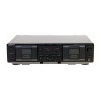
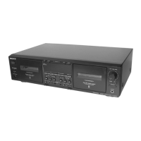
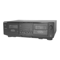
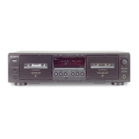
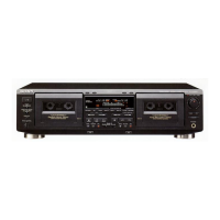
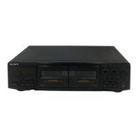
Identifies and labels all controls on the front panel of the unit.

Section 2: Disassembly Procedures

Panel, Mechanism, Base, and Motor Removal

Groups disassembly steps for front panel, mechanism deck, fitting base, and motors.

Head Deck Assembly Removal

Detailed steps for removing the head deck assembly.

Section 3: Mechanical Adjustments

Torque Measurement Procedures

Specifies torque values required for various mechanical adjustments.

Section 4: Electrical Adjustments

Precautions, Test Mode, and Key Adjustments

Covers general precautions, test mode, and major electrical alignment procedures.

Section 5: Diagrams

IC Pin Descriptions and Board Locations

Details pin assignments for ICs and illustrates the physical placement of circuit boards.

Main Section Printed Wiring Boards and Schematics

Covers PWB layout and schematic for the main circuit board.

Main Section Schematic Diagrams (1/4 to 4/4)

References the four parts of the main circuit schematic diagram.

Power and Panel Sections PWBs and Schematics

Covers PWBs and schematics for power supply and panel control sections.

Deck A Section PWBs and Schematics

Provides PWB layouts and circuit diagrams for Deck A.

Deck B Section PWBs and Schematics

Provides PWB layouts and circuit diagrams for Deck B.

Dolby-S Section PWBs and Schematics

Provides PWB layouts and circuit diagrams for the Dolby-S section.

Integrated Circuit (IC) Block Diagrams

Visual representations of the functional blocks within key integrated circuits.

Section 6: Exploded Views

Component Exploded Views

Covers exploded views for case, chassis, cassette holder, and front panel assemblies.

Tape Mechanism Exploded Views

Covers exploded views for tape mechanism sections 1 and 2.

Section 7: Electrical Parts List

Audio Boards Parts Lists

Detailed list of components for the Audio Boards A and B.

Dolby-S and FL Boards Parts Lists

Detailed lists of components for the Dolby-S and FL boards.

Headphone, Leaf Switch Boards Parts Lists

Lists of components for the headphone and leaf switch boards.

Main Parts List

Main Board Components List

Detailed list of components for the main board.

Main Board ICs, Transistors, Resistors, and Other Components

Lists ICs, transistors, resistors, and other components for the main board.

Rec Vol Board Parts List

Rec Vol Board Components List

Detailed list of components for the Rec Vol board.

Switch and Transformer Board Components List

Lists of components for switch and transformer boards.

Miscellaneous and Accessory Parts

Accessories, Packing Materials, and Hardware Lists

Groups lists of accessories, packing materials, and hardware.

Related product manuals