Do you have a question about the Sony TC-WE635 and is the answer not in the manual?
Details the recording system and fast-winding times.
Specifies the frequency response for different tape types.
Procedure for checking AC leakage current from metal parts.
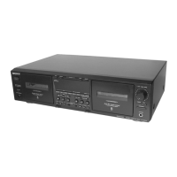
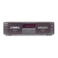
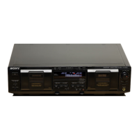
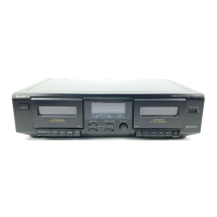
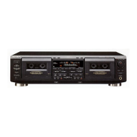
Identifies and labels the various controls on the front panel.
Steps for removing the external case of the unit.
Procedure for removing the front panel assembly.
Steps for removing the cassette lid assembly.
Procedure for removing the mechanism deck assembly.
Steps for removing the leaf switch (REC/PB) board.
Steps for removing the pinch lever assemblies.
Steps for removing the flywheel assemblies.
Steps for removing the mechanical block assembly.
Steps for removing the head relay (REC/PB) board.
Procedure for entering service mode for button and display checks.
Procedure for measuring tape transport torque.
Settings for standard input and output signal levels.
Instructions for using test tapes and entering specific test modes.
Procedure for aligning the record/playback head azimuth.
Procedure for adjusting tape speed accuracy.
Procedure for setting the playback output level.
Adjustment for bias consumption current.
Procedure for setting the record level.
Procedure for adjusting the record bias.
Identifies the physical location of all circuit boards.
Illustrates expected signal waveforms for reference.
Component layout for the main printed wiring board.
Electrical schematic for the main board, part 1 of 4.
Electrical schematic for the main board, part 2 of 4.
Electrical schematic for the main board, part 3 of 4.
Electrical schematic for the main board, part 4 of 4.
Component layout for the deck section printed wiring board.
Electrical schematic for the deck section.
Electrical schematic for the display section.
Component layout for the display section printed wiring board.
Electrical schematic for the panel section.
Component layout for the panel section printed wiring board.
Electrical schematic for the power supply section.
Component layout for the power section printed wiring board.
Details the pin assignments for integrated circuits.
Exploded view illustrating the unit's case components.
Exploded view illustrating the unit's chassis components.
Exploded view illustrating the cassette holder assembly.
Exploded view illustrating the front panel components.
Exploded view illustrating the tape transport mechanism.
Parts list for head relay, leaf switch, and main board components.
Parts list for main and panel board components.
Detailed parts list for the main board.
Detailed parts list for the panel board.
| Brand | Sony |
|---|---|
| Model | TC-WE635 |
| Category | Cassette Player |
| Language | English |