Do you have a question about the Sony TC-WE525 and is the answer not in the manual?
Details recording system, fast winding, bias, S/N ratio, and harmonic distortion.
Specifies frequency response range and wow/flutter measurements.
Covers line inputs/outputs, power requirements, dimensions, mass, and accessories.
Outlines safety checks, including AC leakage testing methods.
Cross-references part numbers with corresponding model designations.
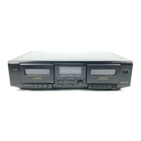
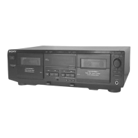
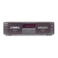
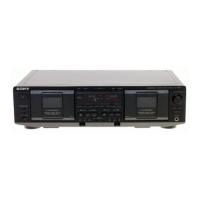
Identifies and describes front panel buttons, switches, and indicators.
Step-by-step instructions for removing the external case and front panel.
Procedures for removing the cassette lid and main mechanism deck assemblies.
Instructions for removing leaf switch boards for Deck A and Deck B.
Guides for disassembling pinch lever and flywheel assemblies for both decks.
Steps for disassembling the mechanical block and head relay boards.
Details mechanical adjustments and required torque measurements for service.
Covers electrical adjustments, test signal levels, and test modes.
Procedure for correctly aligning the record/playback head azimuth.
Steps for calibrating tape speed and playback level for optimal performance.
Adjustment procedure for bias consumption current on Deck B.
Details record level and record bias adjustments for Deck B.
Pinouts and descriptions for system controller IC801.
Explains common notes for printed wiring boards and schematic diagrams.
Printed wiring board layout for the main section of the device.
Part 1 of the main board schematic diagram.
Part 2 of the main board schematic diagram.
Part 3 of the main board schematic diagram.
Printed wiring board layouts for display, power, direction, and recvol boards.
Schematic diagrams for the panel section boards.
Printed wiring board layouts for power supply boards.
Schematic diagrams for the power supply section.
Printed wiring board layout for Deck A's leaf switch board.
Printed wiring board layout for Deck B's leaf switch board.
Exploded view diagram of the unit's external case.
Exploded view diagram of the unit's internal chassis.
Exploded view diagram of the cassette holder assembly.
Exploded view diagram of the front panel assembly.
Exploded view diagram of the tape mechanism section.
Lists resistors, variable resistors, and switches with part numbers.
Lists capacitors, connectors, ICs, and diodes with part numbers.
Lists included connection cords and instruction manuals for various regions.
Lists common hardware items such as screws and lugs used in assembly.
| Track System | 4-track, 2-channel stereo |
|---|---|
| Tape Speed | 4.8 cm/s |
| Motor | DC Servo Motor |
| Signal to Noise Ratio (Normal Tape) | 58dB |
| Power Supply | AC 120V, 60Hz |
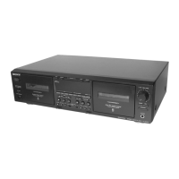
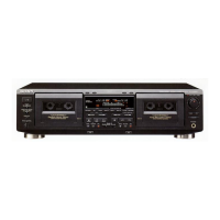
| Type | Double Cassette Deck |
| Frequency Response (Normal Tape) | 30 Hz - 14 kHz |
| Frequency Response (Chrome Tape) | 30 Hz - 16 kHz |
| Frequency Response (Metal Tape) | 30Hz to 17kHz |
| Wow and Flutter | 0.08% (W.R.M.S.) |
| Inputs | Line In |
| Outputs | Line Out, Headphone |
| Dimensions | 430 x 120 x 300mm |