– 11 –
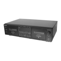
Record/Playback Head Azimuth Adjustment
DECK A DECK B
Procedure:
1. Forward Playback Mode
2. Turn the adjustment screw for the maximum output levels. If
these levels do not match, turn the adjustment screw until both
of output levels match together within 1 dB.
3. Playback Mode
4. Change the reverse playback mode and repeat the steps 1 to 3.
5. After the adjustment, lock the adjustment screws with suitable
locking compound.
Adjustment Location: –record/playback head–
–
+
set
test tape
P-4-A100
(10 kHz, –10 dB)
level meter
LINE OUT
47 k
Ω
within
1 dB
within
1 dB
output
level
R-CH
peak
R-CH
peak
L-CH
peak
L-CH
peak
screw
position
screw position
–
+
–
+
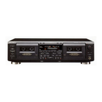
VH
Screen Pattern
set
In phase 45˚ 90˚ 135˚ 180˚
good wrong
47 k
Ω
47 k
Ω
L-CH
R-CH
test tape
P-4-A100
(10 kHz, –10 dB)
LINE OUT
oscilloscope
forward side
reverse side
adjustment screws
Tape Speed Adjustment DECK A DECK B
Procedure:
–Forward Playback Mode–
(High speed adjustment)
1. Set to test mode. (Refer to page 10.)
2. Set to FWD playback mode.
3. Twice pressing the HIGH/NORMAL switch.
4. Adjust RV316 (DECK A), RV416 (DECK B) so that the
frequency counter reading becomes 5,980 ± 20 Hz.
5. Release test mode after adjustment is completed.
(Normal speed adjustment)
1. Set to FWD playback mode.
2. Adjust RV317 (DECK A), RV417 (DECK B) so that the
frequency counter reading becomes 3,000 ± 10 Hz.
(Pitch control adjustment) (DECK A) (TC-WE525 only)
1. Push the PITCH CONTROL switch.
2. Set RV986 (PITCH CONTROL knob) to mechanical center.
3. Set to FWD playback mode.
4. Adjust RV318 so that the frequency counter reading becomes
2,990 ± 10 Hz.
Frequency difference between the beginning and the end of the tape
should be within ± 3%.
Frequency difference between the deck A and deck B the beginning
of the tape should be within ± 1.5%.
Adjustment Location: MAIN board (See page 13.)
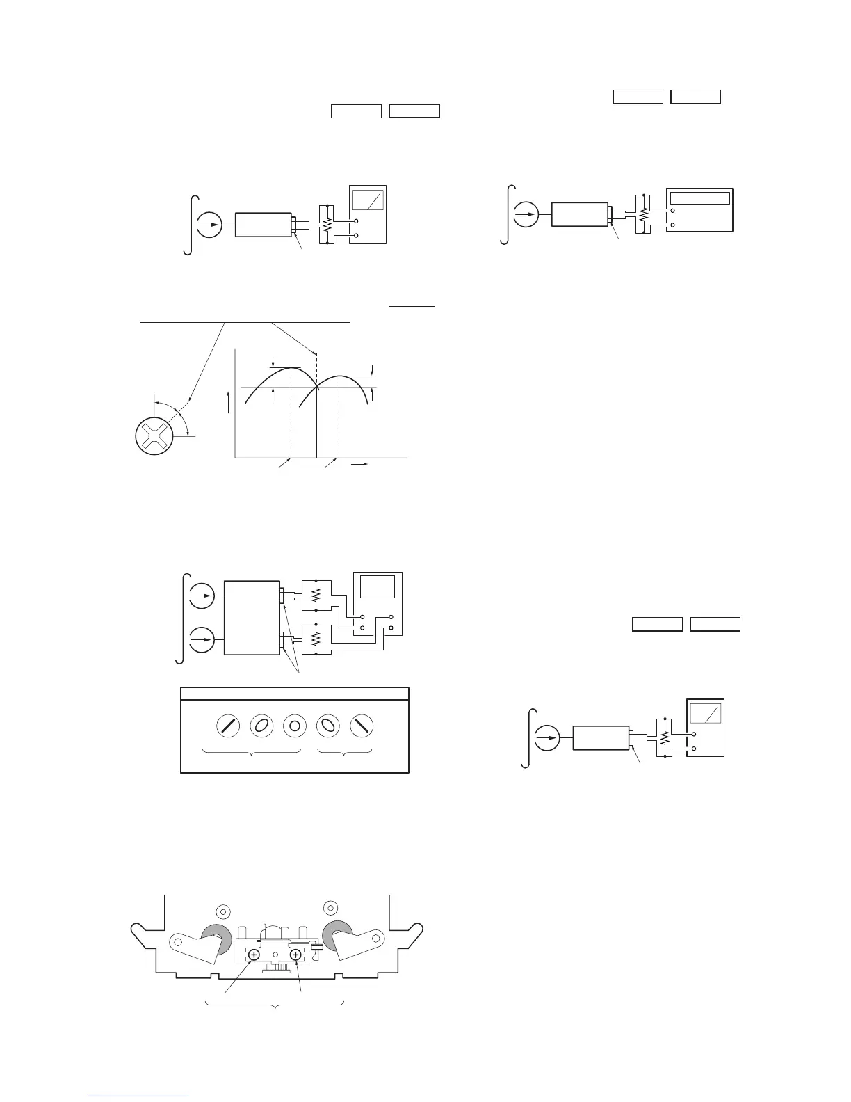
Playback Level Adjustment DECK A DECK B
Procedure:
–Forward Playback Mode–
–
+
set
frequency counter
47 k
Ω
LINE OUT
test tape
WS-48B
(3 kHz, 0 dB)
Adjust DECK A : RV111 (L-CH), RV211 (R-CH) and
DECK B : RV121 (L-CH), RV221 (R-CH) so the level meter read-
ing becomes the adjustment limits below.
Adjustment Value:
LINE OUT level : –7.7 ± 0.5 dB (0.301 to 0.338 V)
Level difference between channels : within 0.5 dB
Confirm that the LINE OUT level does not change in playback mode
while changing the mode from playback to stop several times.
Adjustment Location: MAIN board (See page 13.)
–
+
set
test tape
P-4-L300
(315 Hz, 0 dB)
level meter
LINE OUT
47 k
Ω
 Loading...