– 10 –
PRECAUTION
1. Clean the following parts with a denatured alcohol-moistened
swab :
record/playback/erase head pinch roller
rubber belts capstan
idlers
2. Demagnetize the record/playback head with a head
demagnetizer.
3. Do not use a magnetized screwdriver for the adjustment.
4. After the adjustments, apply suitable locking compound to the
parts adjusted.
5. The adjustments should be performed with the rated power
supply voltage unless otherwise noted.
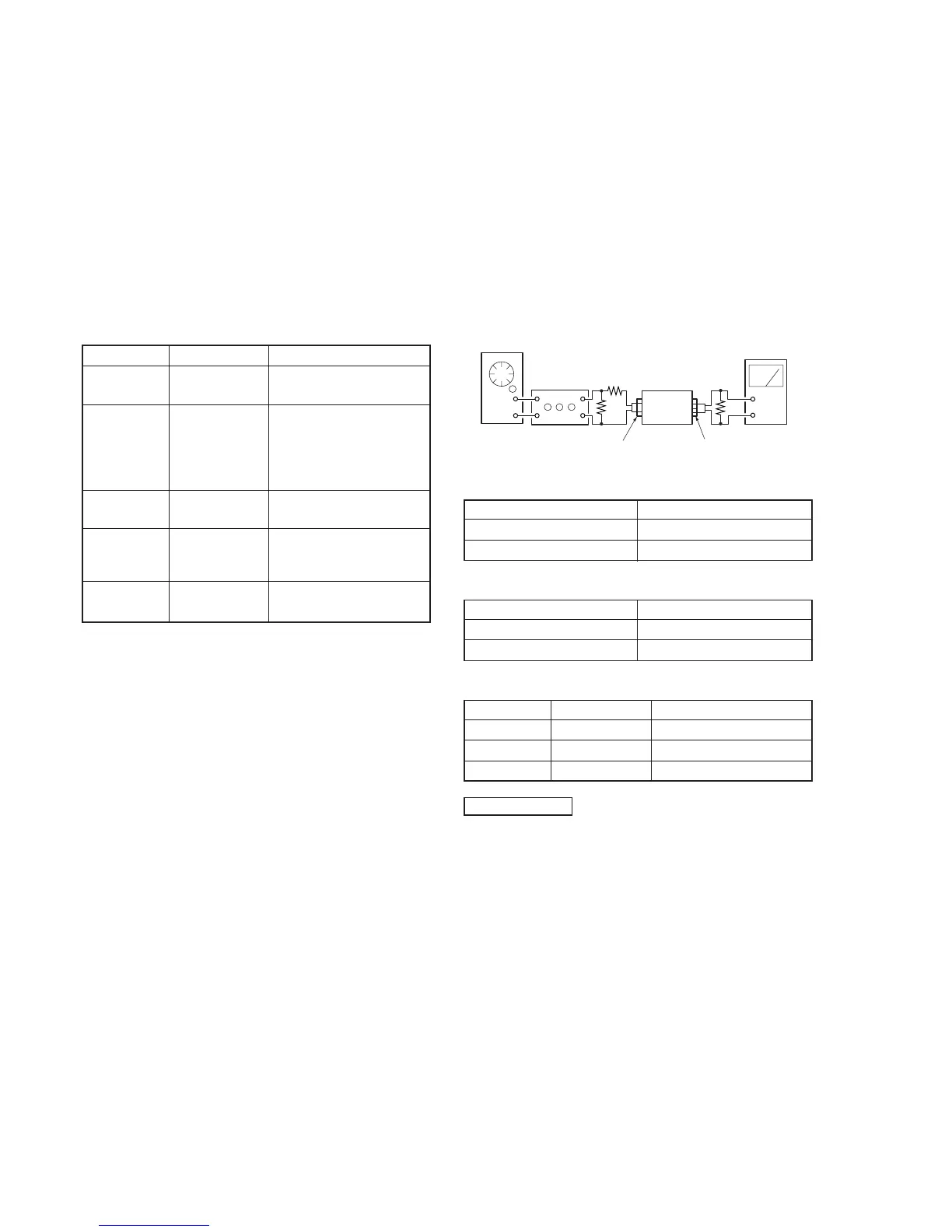
Torque Measurement
Mode Torque meter Meter reading
Forward CQ-102C
30 to 65 g • cm
(0.42 to 0.90 oz • inch)
DECK A : 1 to 6 g • cm
Forward (0.014 to 0.083 oz • inch)
back CQ-102C
tension DECK B : 2 to 9 g • cm
(0.028 to 0.125 oz • inch)
Reverse CQ-102RC
30 to 65 g • cm
(0.42 to 0.90 oz • inch)
Reverse
1 to 6 g • cm
back CQ-102RC
(0.014 to 0.083 oz • inch)
tension
FF/REW CQ-201B
70 to 120 g • cm
(0.97 to 1.67 oz • inch)
SECTION 4
ELECTRICAL ADJUSTMENTS
SECTION 3
MECHANICAL ADJUSTMENTS
PRECAUTION
1. The adjustment should be performed in the publication.
(Be sure to male playback adjustment at first.)
2. The adjustments and measurement should be performed for both
L-CH and R-CH.
• Switch position
DOLBY NR switch : OFF
DIRECTION MODE switch : A
• Standard record position :
Deliver the standard input signal level to input jack and set
the REC LEVEL control to obtain the standard output signal
level as follows.
– Record Mode–
0 dB = 0.775 V
Standard Input Level
Input terminal LINE IN
source impedance 10 kΩ
input signal level 0.5 V (–3.8 dB)
Standard Output Level
Output terminal LINE OUT
load impedance 47 kΩ
output signal level 0.5 V (–3.8 dB)
Test Tape
Tape Contents Use
P-4-A100 10 kHz, –10 dB Azimuth Adjustment
WS-48B 3 kHz, 0 dB Tape Speed Adjustment
P-4-L300 315 Hz, 0 dB PB Level Adjustment
set
–
+
AF OSC
attenuator
10 k
Ω
600
Ω
LINE IN
level meter
LINE OUT
47 k
Ω
Test Mode
1. Turn ON power switch pressing “REC MUTING” and “)”
(FF) (DECK A) at the same time.
At first, all the fluorescent indicator light up, then the system
returns to normal display. (However, “0. 00” is not displayed on
the counter.)
2. To release the test mode, turn OFF the power switch.
 Loading...