– 3 –
TABLE OF CONTENTS
1. GENERAL
1-1. Location of Controls ........................................................... 4
2. DISASSEMBLY
2-1. Case ..................................................................................... 5
2-2. Front Panel Assy ................................................................. 5
2-3. Cassette Lid Assy (Deck A/B) ............................................ 6
2-4. Mechanism Deck Assy (Deck A/B) .................................... 6
2-5. Leaf SW (A) board (Deck A),
Leaf SW (B) board (Deck B) .............................................. 7
2-6. Pinch Lever (FWD)/(REV) Assy (Deck A/B)..................... 8
2-7. Flywheel (FWD)/(REV) Assy (Deck A/B) ......................... 8
2-8. Mechanical Block Assy (Deck A/B) ................................... 9
2-9. Head Relay (PB) Board (Deck A),
Head Relay (REC) Board (Deck B) .................................... 9
3. MECHANICAL ADJUSTMENTS ............................... 10
4. ELECTRICAL ADJUSTMENTS................................. 10
5. DIAGRAMS
5-1. IC Pin Description ............................................................. 14
5-2. Circuit Boards Location .................................................... 16
5-3. Printed Wiring Boards –Main Section– ............................ 17
5-4. Schematic Diagram –Main Section (1/3)– ........................ 19
5-5. Schematic Diagram –Main Section (2/3)– ........................ 21
5-6. Schematic Diagram –Main Section (3/3)– ........................ 23
5-7. Printed Wiring Boards –Panel Section– ............................ 25
5-8. Schematic Diagram –Panel Section– ................................ 27
5-9. Printed Wiring Boards –Power Section–........................... 29
5-10. Schematic Diagram –Power Section– ............................... 31
5-11. Printed Wiring Board –Deck A Section–........................... 32
5-12. Schematic Diagram –Deck A Section– ............................. 32
5-13. Printed Wiring Board –Deck B Section– .......................... 33
5-14. Schematic Diagram –Deck B Section– ............................. 33
6. EXPLODED VIEWS
6-1. Case Section ...................................................................... 34
6-2. Chassis Section ................................................................. 35
6-3. Cassette Holder Section .................................................... 36
6-4. Front Panel Section ........................................................... 37
6-5. Tape Mechanism Section .................................................. 38
7. ELECTRICAL PARTS LIST ........................................ 39
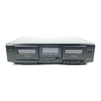
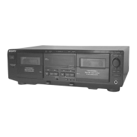
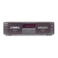
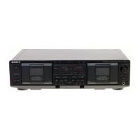
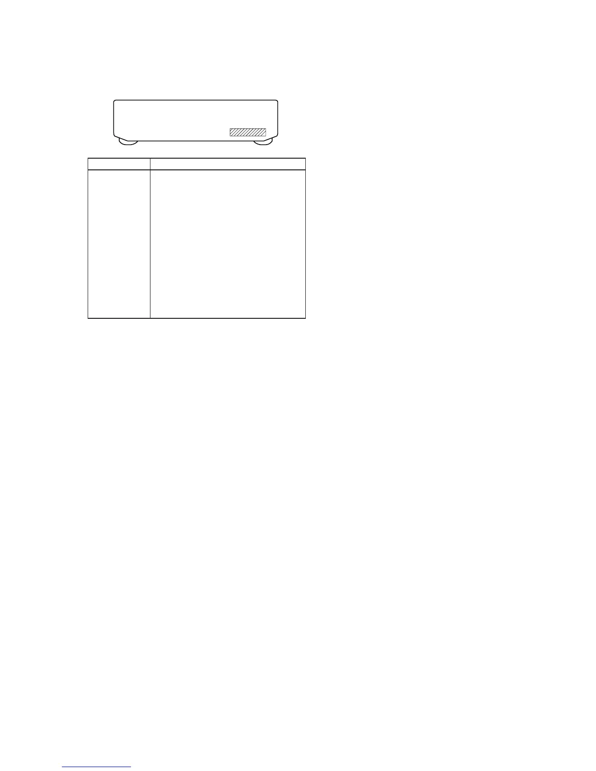
MODEL IDENTIFICATION
–Back panel–
Part No.
Part No. Model
3-021-244-0π TC-WE425 : US model
3-021-244-1π TC-WE425 : CND model
3-021-244-2π TC-WE525 : AEP model
3-021-244-3π TC-WE525 : UK model
3-021-244-4π TC-WE425 : AUS model
3-021-244-5π TC-WE425 : SP, MY model
3-021-244-6π TC-WE425 : CH model
3-021-245-0π TC-WR681 : US model
3-021-245-1π TC-WR681 : AEP model
3-021-245-2π TC-WR681 : E model
3-021-245-3π TC-WR681 : AUS model
3-021-245-4π TC-WR681 : SP model
• Abbreviation
CND : Canadian model
AUS : Austrarian model
SP : Singapore model
MY : Malaysia model
CH : Chinese model
 Loading...