2
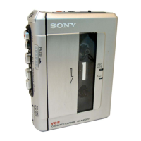
TCM-450DV
TABLE OF CONTENTS
1. GENERAL ................................................................... 2
2. DISASSEMBLY.......................................................... 3
2-1. Cabinet (Rear) ......................................................... 3
2-2. Main Board ............................................................. 4
2-3. Mechanism Deck (MT-450-175)............................. 4
2-4. Belt (Counter), Belt (Cap)S,
M901 (Capstan/Reel Motor), HRP901
(REC/PB Head), HE901 (ERASE HEAD) ............. 5
2-5. Cassette Lid Assy, Led Board ................................. 5
3. MECHANICAL ADJUSTMENTS ....................... 6
4. ELECTRICAL ADJUSTMENTS ......................... 6
5. DIAGRAMS
5-1. Block Diagrams....................................................... 7
5-2. Printed Wiring Board –MAIN Section (Side A) – .. 8
Printed Wiring Board –MAIN Section (Side B) – .. 9
5-3. Schematic Diagram –MAIN Section (1/2) –........... 10
5-4. Schematic Diagram –MAIN Section (2/2) –........... 11
5-5. IC BLOCK DIAGRAMS ........................................ 12
6. EXPLODED VIEWS
6-1. Cassette Lid, Cabinet (Rear) Section ...................... 13
6-2. Cabinet (Front) Section ........................................... 14
6-3. Mechanism Deck Section-1 (MT-450-175) ............ 15
6-4. Mechanism Deck Section-2 (MT-450-175) ............ 16
7. ELECTRICAL PARTS LIST ................................ 17
Flexible Circuit Board Repairing
• Keep the temperature of the soldering iron around 270 ˚C dur-
ing repairing.
• Do not touch the soldering iron on the same conductor of the
circuit board (within 3 times).
• Be careful not to apply force on the conductor when soldering
or unsoldering.
Notes on chip component replacement
• Never reuse a disconnected chip component.
• Notice that the minus side of a tantalum capacitor may be dam-
aged by heat.
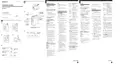
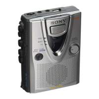
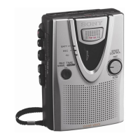
SECTION 1
GENERAL
This section is extracted from
instruction manual.
REC/BATT
REC TIME/
PLAY MODE*
VOR
TAPE COUNTER
x STOP
m REW/REVIEW
PAUSE .
MIC (PLUG
IN POWER)*
EAR
Microphone
DC IN 3V
z
REC
Tape counter
reset button
* The button/jack has a tactile dot.
 Loading...