— 3 —
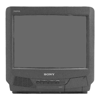
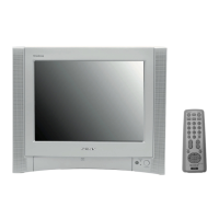
KV-13M42/13M52/13M53/14MB42/14MB42C
Section Title Page
Warnings and Cautions ............................................................................................................................................................... 4
Self-Diagnostic Function ............................................................................................................................................................. 4
Safety Check Out Instructions .................................................................................................................................................... 7
1. GENERAL ............................................................................................................................................................8
2. DISASSEMBLY
2-1. Rear Cover Removal .................................................................................................................................................... 12
2-2. A Board Removal .......................................................................................................................................................... 12
2-3. Service Position ............................................................................................................................................................ 12
2-4. Picture Tube Removal .................................................................................................................................................. 13
3. SET-UP ADJUSTMENTS
3-1. Beam Landing ............................................................................................................................................................... 14
3-2. Convergence ................................................................................................................................................................. 15
3-3. Focus ............................................................................................................................................................................ 16
3-4. Screen (G2)................................................................................................................................................................... 16
3-5. Method of Setting the Service Adjustment Mode ......................................................................................................... 16
3-6. White Balance Adjustments.......................................................................................................................................... 16
4. SAFETY RELATED ADJUSTMENTS
4-1. R582 Confirmation Method (HV Hold-Down Confirmation and Readjustments) .................................................... 17
4-2. B+ Voltage Confirmation and Adjustment .................................................................................................................... 17
5. CIRCUIT ADJUSTMENTS
5-1. Setting the Service Adjustment Mode .......................................................................................................................... 19
5-2. Memory Write Confirmation Method............................................................................................................................. 19
5-3. Adjust Buttons and Indicators....................................................................................................................................... 19
5-4. A Board Adjustments ....................................................................................................................................................22
6. DIAGRAMS
6-1. Block Diagram............................................................................................................................................................... 27
6-2. Circuit Board Location .................................................................................................................................................. 30
6-3. Printed Wiring Boards and Schematic Diagrams......................................................................................................... 30
• A Board ......................................................................................................................................................................33
• C Board ....................................................................................................................................................................... 39
6-4. Semiconductors ............................................................................................................................................................ 42
7. EXPLODED VIEW
7-1. Chassis ......................................................................................................................................................................... 43
8. ELECTRICAL PARTS LIST ................................................................................................................................................ 44
TABLE OF CONTENTS
 Loading...