EasyManua.ls Logo

Sony TRINITRON KV-1442 - Page 34

Sony TRINITRON KV-1442
35 pages
Print Icon
To Next Page IconTo Next Page
To Previous Page IconTo Previous Page
Loading...
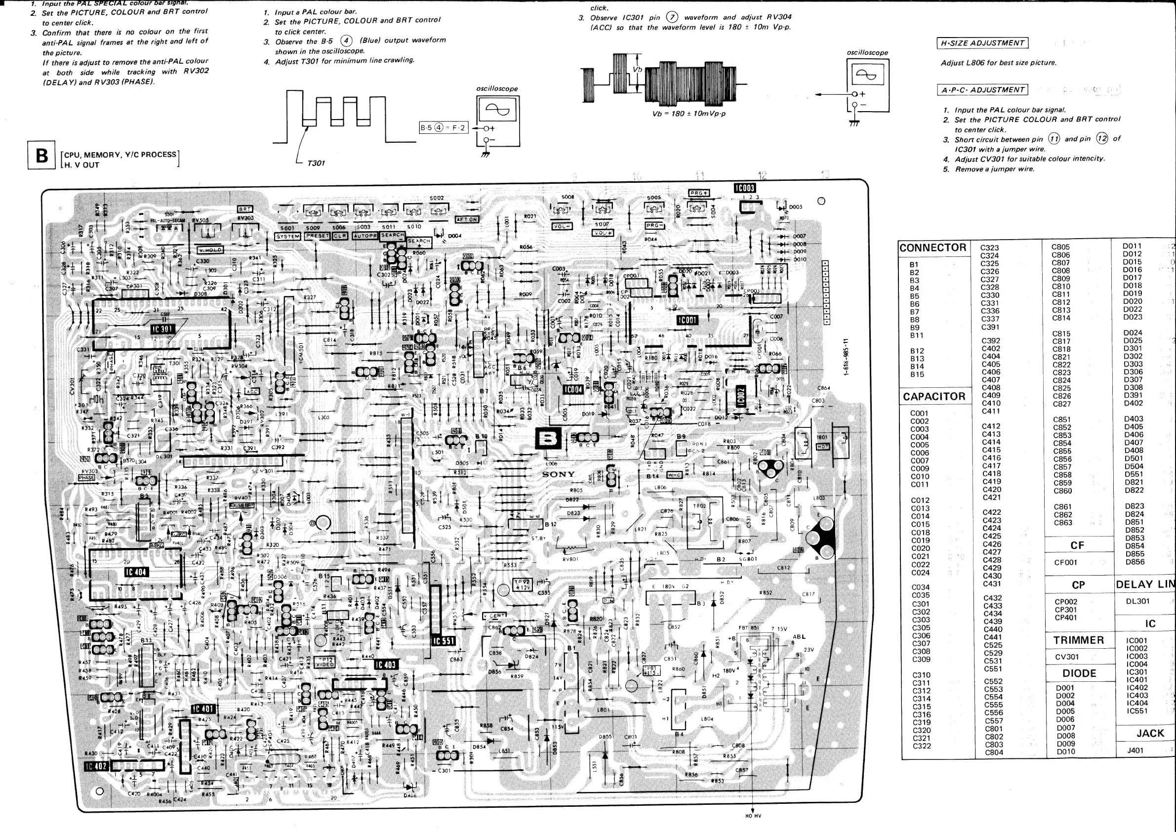
1.
Input
the
PA
z
AL
colour
ba
gnal.
2
Set
the
PICTURE,
COLOUR
and
BRT
control
1.
Input
a
PAL
colour
bar.
click.
to
center
click.
2.
Set
the
PICTURE,
COLOUR
and
BRT
control
3.
Observe
1C301
pin
@)
waveform
and
adjust
RV304
3.
Confirm
that
there
is
no
colour
on
the
first
to
click
center.
(ACC)
so
that
the
waveform
level
is
180
+
10m
Vp-p.
anti-PAL
signal
frames
at
the
right
and
left
of
2.
Observe
the
B-5
(4)
(Blue)
output
waveform
the
picture.
shown
in
the
oscilloscope.
:
H+SIZE
ADJUSTMENT
If
there
is
adjust
to
remove
the
anti-PAL
colour
4.
Adjust
T301
for
minimum
line
crawling.
oscilloscope
at
both
side
while
tracking
with
RV302
Adjust
L806
for
best
size
picture.
(DELAY)
and
RV303
(PHASE).
oscilloscope
| |
|
O+
A+P*C*
ADJUSTMENT
:
OT
Lhe
Vb
=
180
+
10mVp-p
L
1.
Input
the
PAL
colour
bar
signal.
54
2.
Set
the
PICTURE
COLOUR
and
BRT
control
[
<
to
center
click.
1
3.
Short
circuit
between
pin
Ga
and
pin
@2
of
eee
MEMORY,
Y/C
PROCESS
1C301
with
a
jumper
wire.
H.
V
OUT
T301
4.
Adjust
CV301
for
suitable
colour
intencity.
44
Ae
en
5.
Remove
a
jumper
wire.
1-618
-985
-11
CAPACITOR
cP
CPO002
CP301
CP401
|
TRIMMER
CVv301
DIODE
D001
Do02.
D004
DO05
DOO06
D007
D008
DOOg
DO10
HO
HV