EasyManua.ls Logo

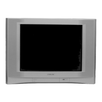
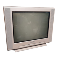
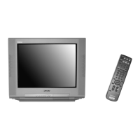
Sony Trinitron KV-20FS100 User Manual

Sony Trinitron KV-20FS100
95 pages
To Next Page IconTo Next Page
Page #1 background imageLoading...
Page #1 background image
TRINITRON
®
COLOR TELEVISION
SERVICE MANUAL
BA-6
CHASSIS
MODEL NAME REMOTE COMMANDER DESTINATION CHASSIS NO.
9-965-922-02
KV-20FS100
RM-Y173 US SCC-S61A-A
KV-20FS100
RM-Y173 CND SCC-S59A-A
KV-20FV300
RM-Y180 US SCC-S61B-A
KV-20FV300
RM-Y180 CND SCC-S59B-A
KV-21FM100
RM-Y172 LATIN NORTH SCC-S60E-A
KV-21FM100
RM-Y172 LATIN SOUTH SCC-S60F-A
KV-21FS100
RM-Y173 LATIN NORTH SCC-S60A-A
KV-21FS100
RM-Y173 LATIN SOUTH SCC-S60B-A
KV-21FV300
RM-Y180 LATIN SOUTH SCC-S60D-A
KV-21FV300
RM-Y180 LATIN NORTH SCC-S60C-A
KV-24FV300
RM-Y180 US SCC-S61C-A
KV-24FV300
RM-Y180 CND SCC-S59C-A
KV-25FV300
RM-Y180 LATIN NORTH SCC-S60G-A
KV-25FV300
RM-Y180 LATIN SOUTH SCC-S60H-A
HISTORY INFORMATION FOR THE FOLLOWING MANUAL:
ORIGINAL MANUAL ISSUE DATE: 2/2002
ALL REVISIONS AND UPDATES TO THE ORIGINAL MANUAL ARE APPENDED TO THE END OF THE PDF FILE.
REVISION DATE REVISION TYPE SUBJECT
2/2002 No revisions or updates are applicable at this time.
2/2002 Supplement - 1 New A Board Schem. and PWB, New CV Board Schem., New M3 Board Schem.,
R039, R565, R1761 P/N Correction.

Table of Contents

Question and Answer IconNeed help?

Do you have a question about the Sony Trinitron KV-20FS100 and is the answer not in the manual?

Sony Trinitron KV-20FS100 Specifications

General IconGeneral
BrandSony
ModelTrinitron KV-20FS100
CategoryTV
LanguageEnglish

Summary

Specifications

Safety Warnings and Precautions

General Safety Warnings

Critical safety advice including handling high voltage and components.

French Safety Notes

Safety advice in French, emphasizing critical components and procedures.

Safety Check-Out Procedures

Leakage Test Procedures

Instructions for performing AC leakage tests on exposed metal parts.

Earth Ground Verification Method

Method for identifying a reliable earth ground connection for testing.

Self-Diagnostic Functions

Diagnostic Indicators and Procedures

Interpretation of LED flash codes and procedures for using the diagnostic screen.

Stopping Diagnostic Display

Method to stop the flashing STANDBY/TIMER LED and exit diagnostic mode.

SECTION 1: Disassembly Procedures

Rear Cover and Chassis Removal

Procedures for removing the rear cover and main chassis assembly.

Service Position and Picture Tube Removal

Proper unit orientation for service and safe picture tube removal.

Anode Cap Handling

Safe procedures for handling and removing the picture tube anode cap.

SECTION 2: Set-Up Adjustments

Picture Alignment Adjustments

Procedures for aligning picture elements like beam landing, convergence, focus, and screen voltage.

Service Mode and White Balance

Method for entering service mode and adjusting white balance for color accuracy.

SECTION 3: Safety Related Adjustments

R565 HV Hold-Down Confirmation

Procedure for confirming and readjusting R565 for HV hold-down safety.

B+ Voltage Confirmation and Adjustment

Confirmation and adjustment of B+ voltage for safe operation.

SECTION 4: Circuit Adjustments

Service Mode and Adjustment Procedures

Steps to enter service mode, confirm adjustments, and use remote controls for calibration.

Detailed Adjustment Items

Comprehensive list of adjustable parameters for various circuit devices like DEF, VP1, VP2, etc.

SECTION 5: Diagrams and Schematics

Circuit Board Locations and PWB/Schematic Info

Identification of board locations and explanation of diagram conventions.

Block Diagram and Schematics

Block diagram and detailed schematic diagrams for system overview.

Specific Board Schematics (A, CV, HR, M3)

Detailed schematic diagrams for A, CV, HR, and M3 boards.

Semiconductor Identification

SECTION 6: Exploded Views

Chassis Exploded Views by Model

Exploded views of chassis assemblies for various models, showing part locations.

SECTION 7: Electrical Parts List

A Board Common and Variant Parts Lists

Lists of common and model-specific components for the A board.

CV, HR, M3 Board Parts Lists

Complete parts lists for CV, HR, and M3 boards.

Accessories and Packing Information

List of included accessories and packing details.
Related product manuals