EasyManua.ls Logo

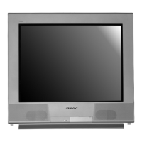
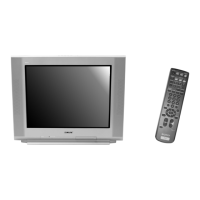
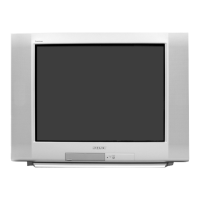
Sony TRINITRON KV-27FS320 User Manual

Sony TRINITRON KV-27FS320
164 pages
To Next Page IconTo Next Page
Page #1 background imageLoading...
Page #1 background image
TRINITRON
®
COLOR TELEVISION
SERVICE MANUAL
BA-6
CHASSIS
MODEL NAME REMOTE COMMANDER DESTINATION CHASSIS NO.
9-965-964-01
KV-27FS320
RM-Y196 US SCC-S61S-A
KV-27FS320
RM-Y196 CANADA SCC-S59N-A
KV-32FS120
RM-Y195 US SCC-S61P-A
KV-32FS120
RM-Y195 CANADA SCC-S59K-A
KV-32FS320
RM-Y196 US SCC-S61T-A
KV-32FS320
RM-Y196 CANADA SCC-S59P-A
KV-34FS120
RM-Y195 LATIN NORTH SCC-S73F-A
KV-34FS120
RM-Y195 LATIN SOUTH SCC-S73G-A
KV-36FS120
RM-Y195 US SCC-S61Q-A
KV-36FS120
RM-Y195 CANADA SCC-S59L-A
KV-36FS120
RM-Y195 HAWAII SCC-S74A-A
KV-36FS320
RM-Y196 US SCC-S61R-A
KV-36FS320
RM-Y196 CANADA SCC-S59M-A
KV-36FS320
RM-Y196 HAWAII SCC-S74B-A
KV-38FS120
RM-Y195 LATIN NORTH SCC-S73G-A
HISTORY INFORMATION FOR THE FOLLOWING MANUAL:
ORIGINAL MANUAL ISSUE DATE: 5/2004
REVISION DATE SUBJECT
5/2004 No revisions or updates are applicable at this time.

Table of Contents

Question and Answer IconNeed help?

Do you have a question about the Sony TRINITRON KV-27FS320 and is the answer not in the manual?

Sony TRINITRON KV-27FS320 Specifications

General IconGeneral
BrandSony
ModelTRINITRON KV-27FS320
CategoryTV
LanguageEnglish

Summary

SPECIFICATIONS

WARNINGS AND CAUTIONS

SAFETY CHECK-OUT

SELF-DIAGNOSTIC FUNCTION

Diagnostic Test Indicators

Explains LED flash codes for error diagnosis.

Display of Standby/Timer LED Flash Count

Visual representation of LED flash counts.

SECTION 1: DISASSEMBLY

1-1. Rear Cover Removal

Procedure for removing the rear cover.

1-2. Chassis Assembly Removal

Steps for removing the chassis assembly.

1-4. Picture Tube Removal

Instructions for safely removing the picture tube.

SECTION 2: SET-UP ADJUSTMENTS

2-5. Method of Setting the Service Adjustment Mode

Procedures to enter and use the service mode.

SECTION 3: SAFETY RELATED ADJUSTMENTS

3-2. B+ Voltage Confirmation and Adjustment

Confirming and adjusting the B+ voltage level.

SECTION 4: CIRCUIT ADJUSTMENTS

4-1. Setting the Service Adjustment Mode

Entering the service adjustment mode via remote.

4-4. Service Data Lists

Lists initial settings for various TV models.

SECTION 5: DIAGRAMS

5-3. Block Diagram and Schematics

High-level block diagram and detailed schematics.

5-4. Semiconductors

Diagrams and descriptions of semiconductor components.

SECTION 6: EXPLODED VIEWS

SECTION 7: ELECTRICAL PARTS LIST

IMPORTANT SAFEGUARDS

Water and Moisture

Precautions regarding water exposure.

Service

Conditions requiring professional service.

Servicing

Warning against self-servicing the TV.

Replacement Parts

Importance of using specified replacement parts.

Safety Check

Post-service safety checks by technician.

Using the Remote Control

Programming the Remote Control

Manufacturer’s Codes

Using your TV Remote Control with Other Equipment

Connecting Your TV

Basic Connections

Connecting Additional Equipment

Connecting a DVD Player using Composite Video (VIDEO/AUDIO L(MONO),R)

Connecting a DVD Player using Component Video (Y, PB, PR/R, L)

Connecting for Video Tape Editing (VCR and Camcorder)

Using Basic Functions

Setting Up the TV

Initial TV setup including Auto Program.

Using the Menus

Using the Video Menu

Using the Audio Menu

Using the Channel Setup Menu

Using the Parental Control Menu

Parental Control

Setting the Rating

Adjusting TV rating limits for content filtering.

Changing your Password

Procedure to change the parental control password.

United States: Selecting Custom Rating Options

Canada: Selecting Custom Rating Options

Using the Timer Menu

Using the Setup Menu

Troubleshooting

General

Common TV problems and their solutions.

Remote Control

Troubleshooting issues with the remote control.

Programming The Remote Control

Steps to program the remote for other devices.

Video

Troubleshooting video display problems.

Audio

Troubleshooting audio output issues.
Related product manuals