K
kyleparkerAug 4, 2025
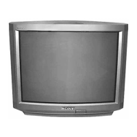
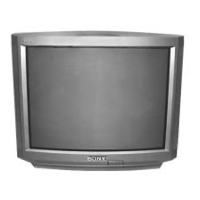
Why my Sony Trinitron KV-32V65 cannot receive any channels when using cable?
- JJoann ClaytonAug 4, 2025
If your Sony TV cannot receive any channels when using cable, the CABLE setting may not be set correctly in the SET UP menu. Ensure that CABLE is set to OFF in the SET UP menu.