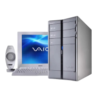
Do you have a question about the Sony VAIO PCV-RS Series and is the answer not in the manual?
Follow all safety labels and warnings for proper operation and maintenance procedures.
Use only specified components to ensure safety characteristics and proper functionality.
Maintain original layout for safety features and proper component placement when mounting or routing.
Verify all components and wiring are correctly reassembled and secure after servicing.
Avoid reusing components and handle sensitive chip components with care, especially capacitors.
Use appropriate soldering temperatures and techniques for flexible circuit boards to prevent damage.
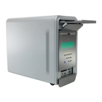
Visual guide for disassembling and identifying parts of the computer's outer casing.
Visual guide for disassembling and identifying internal drive components like HDD and ODD.
Visual guide for disassembling and identifying internal electronic boards and modules.
Visual guide for disassembling and identifying the main structural frame and support components.
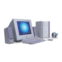
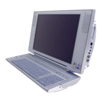
Illustrates optional or bundled peripheral devices and their part numbers.
Comprehensive list of all parts, their part numbers, and model compatibility.
Lists alternative parts available for substitution when original parts are unavailable.
Overview of the disassembly and assembly process for various computer components.
Visual guide showing the routing and connection points of internal harnesses within the PC.
Step-by-step guide for safely removing the side cover and front panel assembly.
Detailed steps for removing the optical drive from the system.
Detailed steps for removing the floppy disk drive.
Procedures for safely removing memory modules from their slots.
Steps for correctly connecting LED indicator harnesses to the motherboard.
Detailed steps for removing the hard disk drive.
Procedures for removing and disconnecting the CNX-211 interface board.
Step-by-step guide for removing IFX and CNX series boards.
Procedures for removing the power supply unit.
Steps for removing the CPU or chassis cooling fan assembly.
Procedures for safely removing and installing the Central Processing Unit.
Steps for removing and installing the chassis cooling fan.
Procedures for removing and installing the modem card.
Steps for removing and installing the graphics card.
Procedures for removing and installing the Mounted PWB ENX-26.
Detailed instructions for removing the motherboard from the chassis.
Visual representation of internal wiring, connectors, and jumper settings on the motherboard.