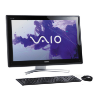
Do you have a question about the Sony VPCF1 Series and is the answer not in the manual?
Overview of the VPCF1 Series block diagram, detailing component connections.
Harness diagram illustrating connections from the top view of the VPCF1 Series.
Harness diagram illustrating connections from the bottom view of the VPCF1 Series.
Detailed listing and illustrations of various screws used in the VPCF1 Series.
Exploded view and parts list for the palmrest assembly and related components.
Exploded view and parts list for the main board and its associated parts.
Exploded view and parts list for the bottom case and its components.
Exploded view and parts list for the cabinet covers and related parts.
Exploded view and parts list for the Optical Disk Drive (ODD) assembly.
Exploded view and parts list for the Hard Disk Drive (HDD) assembly.
Exploded view and parts list for the Liquid Crystal Display (LCD) assembly.
Exploded view and parts list for accessories like power cords and adapters.
Location and configuration details for DIP switches on the VPCF1 Series.
Step-by-step instructions for removing and installing the CPU safely.
Guidelines for properly handling the motherboard during service procedures.
| Series | VPCF1 Series |
|---|---|
| Maximum Memory | 8 GB |
| CPU | Intel Core i7 |
| Memory | 4GB DDR3 |
| RAM | DDR3 SDRAM |
| Graphics Memory | 1GB |
| Display | 16.4" (1920x1080) Full HD |
| Hard Drive | 500GB HDD |
| Optical Drive | Blu-ray Disc Drive |
| Operating System | Windows 7 Home Premium |
| Wireless | 802.11b/g/n |
| Ports | HDMI, VGA, Headphone, Microphone |
| Bluetooth | Bluetooth Standard Version 2.1 + EDR |
| Webcam | Built-in MOTION EYE camera |