EasyManuals Logo

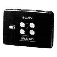
Sony Walkman WM-EX511 User Manual

Sony Walkman WM-EX511
22 pages
To Next Page IconTo Next Page
To Previous Page IconTo Previous Page
Page #7 background imageLoading...
Page #7 background image
3-3.
OPENING
OF
MAIN
BOARD
@
Screw
(M1.4)
@
Screw
(M1.4x2.0)
Screw
(M1.7x4)
@
Screw
(M1.4x2.0)
Remove
the
solder.
(Battery
terminal
board
(+)
assembly)
—~@
Open
the
main
board
@
Flexible
board
(Magnetic
head)
Remove
the
solder.
(Terminal
board)
3-4.
BELT
Belt
Cc
in
the
arrow
direction.
SECTION
4
SECTION
5.
ADJUSTMENTS
DIAGRAMS
4-1.
MECHANICAL
ADJUSTMENTS
PRECAUTION
1.
Clean
the
following
parts
with
a
denatured-alcohol-
moistened
swab
:
playback
head
rubber
belts
capstan
idlers
pinch
roller
.
Demagnetize
the
playback
head
with
a
head
demagnetizer.
Do
not
use
a
magnetized
screwdriver
for
the
adjustments.
After
the
adjustments,
apply
suitable
locking
compound
to
the
parts
adjusted.
5.
The
adjustments
should
be
performed
with
the
rated
power
supply
voltage
(1.3V)
unless
otherwise
noted.
Rw
Torque
Measurement
EWD
21—
38
g*cm
(0.29
0.53
oz
«
inch)
CQ102C
FWD
0.5
—3
g°*cm
Back
Tension
(0.01
0.04
oz
¢
inch)
21
38
g*cm
REV
PREV
CQ102RC
(0.29
0.53
oz
«
inch)
0
F
EW
REV
5—3g°*cm
Back
Tension
(0.01
0.04
oz
«
inch)
CQ201B
Tape
Pulling
Force
Measurement
Meter
Reading
more
than
60
g
*
cm
(more
than
0.84
oz
»
inch)
more
than
35
g
(more
than
1.23
oz)
5-1.
BLOCK
DIAGRAM
4-2.
ELECTRICAL
ADJUSTMENTS
10301
EQ
AMP,
EX
BBB,
PW
OUTPUT
AMP
PRECAUTION
1.
Power
supply
voltage
:
1.3V.
pi
nvanek
2.
Switch
position
HEAD
_
DOLBY
NR
switch
:
OFF
Len
=
&
sy
EX
DBB
switch
:
NORM
J.
7
|
=
a
_—
Test
Tape
Ron
—=
|
(3)
>
Type
|
‘Signal
o—
——S
SS
*
a
Len
—~
&
_
J301
'
!
!
i
H
o|
4
|
|
REMOTE
0
1
t
ON
°
i
Q
§
$304
H
H
WS-48A
3
kHz,
0
dB
Tape
Speed
Adjustment
FeV
wey
TAPE
SPEED
ADJUSTMENT
Ren
V
REF
5
ators
hn
NS
MUTE
Procedure
:
test
NORM
<—
MID
—<—~MAX
=
WS-48A
frequency
8303
F
(3
kHz,
0
dB)
18Q
counter
EX
OBB
:
PHONE
JACK
1.
Play
back
WS-48A
(tape
center
portion)
in
FWD
mode.
Adjust
the
RV601
so
that
the
frequency
counter
reads
3,000
Ww
+
30
Hz.
j
1701
2.
Play
back
WS-48A
(tape
center
portion)
in
REV
mode.
a
ae
Confirm
that
the
reading
of
frequency
counter
is
within
2.5%
from
the
reading
in
step
1.
ls]
e708
so
|
YR
®
.
.
$710
$709
<>
Adjustment
Parts
Location
diagram
:
[=
|
BATT
LED
MAIN
BOARD
(SIDE
B)
ry
§703
HOLO
aah.
IC701
Former
type
only.
5704
MODE)
[BL_SKIP'
©
ON
Pi,
res
ANS
:
|
1
foun:
[enol
\
RV601
I
rh
>
*
Signal
path,
Vaan
>>
‘PB
Baal
10601
1.54
BRY
BATTERY
.
SIZE
“AA™
QEC
BESIGNATION
Ré)
Q302,
303
a
IP.
1.5V
10301
.
ui
pc
IN
1.5V
5
e
oe}
09
T501
is)
1c301
CAMMIUM
#
BATTERY
—~8—
|
—9—
—10—
WM-EX511/EX618

Questions and Answers:

Question and Answer IconNeed help?

Do you have a question about the Sony Walkman WM-EX511 and is the answer not in the manual?

Sony Walkman WM-EX511 Specifications

General IconGeneral
BrandSony
ModelWalkman WM-EX511
CategoryCassette Player
LanguageEnglish

Related product manuals