EasyManua.ls Logo

Sony WM-EX668 User Manual

Sony WM-EX668
18 pages
To Next Page IconTo Next Page
Page #1 background imageLoading...
Page #1 background image
Ver 1.2 2000. 03
With SUPPLEMENT 1 (9-923-312-81)
WM-EX655/EX668
AEP Model
UK Model
WM-EX668
Tourist Model
WM-EX655
CASSETTE PLAYER
SPECIFICATIONS
MICROFILM
SERVICE MANUAL
Model Name Using Similar Machanism NEW
Tape Transport Mechanism Type MT-WMEX655-125
Dolby noise reduction manufactured under license from
Dolby Laboratories Licensing Corporation.
“DOLBY” and the double-D symbol a are trademarks of
Dolby Laboratories Licensing Corporation.
Tape Player section and general
Frequency response (a NR switch off)
30 – 18,000Hz
Output
Headphones (2 REMOTE jack)
Load impedance 8 – 300ohms
Power output
4mW + 4mW at DC operation
Power requirements
1.5V DC
Rechargeable battery (NC-6WM), 1.2V, 600mAH, Ni-Cd) One R6
(size AA) battery
Battery life (Aprrox. hours)
Rechargeable NC-6WM 9
Fully charged
Sony R6P (SR) 9
Sony alkaline LR6 (WM) 36
Rechargeable NC-6WM 45
Sony alkaline LR6 (WM)
Used together
Dimensions
Approx. 108.9 x 80 x 21.3 mm (w/h/d)
Weight
Approx. 150g (Main unit)
Approx. 215g (incl. Headphones with remote control, Recharge-
able battery NC-6WM (S), Type (C-60-HF))
Supplied Accessories
• Battery charger (1)
• Rechargeable battery (NC-6WM, 1.2V 600mAh, Ni-Cd) (1)
• Battery case (1) (WM-EX655)
• Stereo earphones with remote control (1) (WM-EX655)
• Carrying pouch (1)
• Rechargeable battery carrying case (1)
• Remote control unit (RM-WME654) (1)
• Sony battery R6P (SR) (1) (WM-EX655)
AC plug adaptor (1) (WM-EX655)
• Clip (1) (WM-EX655)
Design and specifications are subject to change without notice.
Photo : WM-EX655
Question and Answer IconNeed help?

Do you have a question about the Sony WM-EX668 and is the answer not in the manual?

Sony WM-EX668 Specifications

General IconGeneral
TypeCassette Player
BrandSony
ModelWM-EX668
Media TypeCassette
FeaturesAuto-Reverse, Dolby B
Power Supply1 x AA battery

Summary

SECTION 1 GENERAL

LOCATION AND FUNCTION OF CONTROLS

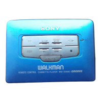
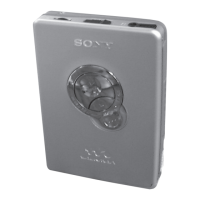
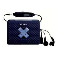
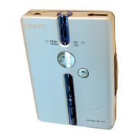
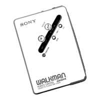
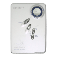
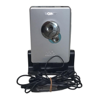
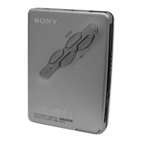
Overview of the main unit and headphone controls.

SECTION 2 SERVICE NOTE

SERVICE MODE

Procedure for operating the mechanism with the audio board open.

SECTION 3 DISASSEMBLY

CASE ASSY REMOVAL

Steps to remove the case assembly.

AUDIO BOARD REMOVAL

Steps to remove the audio board.

SECTION 4 ADJUSTMENTS

MECHANICAL ADJUSTMENTS

Procedures for mechanical calibration.

ELECTRICAL ADJUSTMENTS

Procedures for electrical calibration.

SECTION 5 DIAGRAMS

EXPLANATION OF IC TERMINALS

Details on IC terminals.

PRINTED WIRING BOARDS

Layouts of printed wiring boards.

SCHEMATIC DIAGRAM

Electrical schematic diagram of the unit.

SECTION 6 EXPLODED VIEWS

CASE SECTION

Exploded view of the case assembly.

AUDIO BOARD SECTION

Exploded view of the audio board section.

MECHANISM DECK SECTION

Exploded view of the mechanism deck.

SECTION 7 ELECTRICAL PARTS LIST

SUPPLEMENT - 1

NO INTERCHANGEABILITY OF MOTORS DUE TO CHANGE OF MECHANISM DECK

Information on motor interchangeability issues.

CAUTION WHEN INSTALLING A NEW MOTOR

Precautions for installing new motors.

CHANGED PARTS LIST

List of updated or changed parts.

Related product manuals