EasyManua.ls Logo

Sony XAV-612BT User Manual

Sony XAV-612BT
70 pages
To Next Page IconTo Next Page
Page #1 background imageLoading...
Page #1 background image
SERVICE MANUAL
Sony Corporation
Published by Sony Techno Create Corporation
Monitor section
Display type: Wide LCD color monitor
Dimensions:
System: TFT active matrix
Number of pixels:
1,152,000 pixels (800 × 3 (RGB) × 480)
Color system:
PAL/NTSC/SECAM/PAL-M/PAL-N automatic
select
Tuner section
(E (PAL), Indian and Australian models)
FM
Tuning range: 87.5 – 108.0 MHz
Antenna (aerial) terminal:
External antenna (aerial) connector
6.1 in
Intermediate frequency: 25 kHz
Usable sensitivity: 9 dBf
Selectivity: 75 dB at 400 kHz
Signal-to-noise ratio (stereo): 80 dB (mono)
Separation at 1 kHz: 50 dB
Frequency response: 20 - 15,000 Hz
AM
Tuning range: 531 – 1,602 kHz
Antenna (aerial) terminal:
External antenna (aerial) connector
Intermediate frequency:
9,124.5 kHz or 9,115.5 kHz/4.5 kHz
Sensitivity: 26 μV
FM
Tuning range:
87.5 - 108.0 MHz (at 100 kHz step)
87.5 - 107.9 MHz (at 200 kHz step)
FM tuning step: 100 kHz/200 kHz switchable
Antenna (aerial) terminal:
External antenna (aerial) connector
Intermediate frequency: 25 kHz
Usable sensitivity: 9 dBf
Selectivity: 75 dB at 400 kHz
Signal-to-noise ratio (stereo): 80 dB (mono)
Separation at 1 kHz: 50 dB
Frequency response: 20 - 15,000 Hz
AM
Tuning range: 530 – 1,710 kHz
Antenna (aerial) terminal:
External antenna (aerial) connector
Intermediate frequency:
9,124.5 kHz or 9,115.5 kHz/4.5 kHz
Sensitivity: 26 μV
Tuner section (E (NTSC) model)
DVD/CD Player section
Signal-to-noise ratio: 120 dB
Frequency response: 10 – 20,000 Hz
Wow and flutter: Below measurable limit
Harmonic distortion: 0.01%
Region code: Labeled on the bottom of the unit
USB Player section
Interface: USB (High-speed)
Maximum current: 1 A
1.5 A (HIGH CHARGE mode)
HDMI in / MHL in section
Interface: HDMI in / MHL in
Incorporates MHL 2 (only MHL)
Maximum current (only MHL): 0.9 A
Wireless Communication
Communication System:
BLUETOOTH Standard version 2.1 + EDR
Output:
BLUETOOTH Standard Power Class 2 (Max. +4
dBm)
Maximum communication range:
Line of sight approx. 10 m (33 ft)*
2
Frequency band:
2.4 GHz band (2.4000 – 2.4835 GHz)
Modulation method: FHSS
Tuner section (Russian model)
FM
Tuning range:
FM1/FM2: 87.5 - 108.0 MHz (at 50 kHz step)
FM3: 65 - 74 MHz (at 30 kHz step)
Antenna (aerial) terminal:
External antenna (aerial) connector
Intermediate frequency: 25 kHz
Usable sensitivity: 9 dBf
Selectivity: 75 dB at 400 kHz
Signal-to-noise ratio (stereo): 80 dB (mono)
Separation at 1 kHz: 50 dB
Frequency response: 20 - 15,000 Hz
MW/LW
Tuning range:
MW: 531 – 1,602 kHz
LW: 153 – 279 kHz
Antenna (aerial) terminal:
External antenna (aerial) connector
Intermediate frequency:
9,124.5kHz or 9,115.5kHz/4.5kHz
Sensitivity: MW: 26 μV, LW: 4 6 μV
*3 BLUETOOTH standard profiles indicate the purpose
of BLUETOOTH communication between devices.
Power amplifier section
Outputs: Speaker outputs
Speaker impedance: 4 – 8 ohms
Maximum power output: 52 W × 4 (at 4 ohms)
General
Outputs:
Video output terminal (rear)
Audio output terminals (front/rear)
Audio output terminal (Z×Z)
Subwoofer output terminal
Power antenna (aerial)/Power amplifier control
terminal (REM OUT) (Except Russian model)
Maximum number of storable phonebook
contacts: 1,000
*2 The actual range will vary depending on factors such
as obstacles between devices, magnetic fields
around a microwave oven, static electricity,
reception sensitivity, antenna’s performance,
operating system, software application, etc.
Power antenna (aerial) relay control terminal (Russian model)
Power amplifier control terminal (Russian model)
Inputs:
Illumination control terminal
Remote controller input terminal
Antenna (aerial) input terminal
Parking brake control terminal
Microphone input terminal
Reverse input terminal
Camera input terminal
AUX audio input terminals
AUX video input terminals
USB ports
HDMI in / MHL in port
Compatible BLUETOOTH Profiles*
3
:
A2DP (Advanced Audio Distribution Profile) 1.2
AVRCP (Audio Video Remote Control Profile) 1.3
HFP (Handsfree Profile) 1.5
PBAP (Phone Book Access Profile)
OPP (Object Push Profile)
SPP (Serial Port Profile)
Design and specifications are subject to change
without notice.
Region code
The region system is used to protect software
copyrights.
The region code is located on the bottom of the
unit, and only DVDs labeled with an identical region
code can be played on this unit.
DVDs labeled can also be played.
If you try to play any other DVD, the message [Disc
playback prohibited by region code.] will appear on
the monitor screen. Depending on the DVD, no
region code may be labeled even though playing
the DVD is prohibited by area restrictions.
Power requirements: 12 V DC car battery
(negative ground (earth))
Dimensions:
Approx. 178 mm × 100 mm × 173 mm
(7
1
/ 8 × 4 × 6
7
/ 8 in) (w/h/d)
Mounting dimensions:
Approx. 182 mm × 111 mm × 160 mm
(7
1
/ 4 × 4
3
/ 8 × 6
3
/ 8 in) (w/h/d)
Mass:
Approx. 2.0 kg (4 lb 7 oz)
Package contents:
Parts for installation and connections (1 set)
Microphone (1)
Remote Commander (1): RM-X271
HDMI connection cable (1): RC-400VH
MHL connection cable (1): RC-500VM
Panel Case (1)
XAV-612BT
SPECIFICATIONS
AV CENTER
9-893-902-01
2013K33-1
©
2013.11
E Model
Australian Model
Russian Model
Ver. 1.0 2013.11
Model Name Using Similar Mechanism XAV-602BT
Mechanism Type MG-614D-189
Optical Pick-up Name TOP1300SE C11
The service manual of the mechanism
deck, used in this model, has been issued
in a separate volume. Please refer to the
service manual of the MG-614 series for
the mechanism deck information.
Question and Answer IconNeed help?

Do you have a question about the Sony XAV-612BT and is the answer not in the manual?

Sony XAV-612BT Specifications

General IconGeneral
BrandSony
ModelXAV-612BT
CategoryCar Receiver
LanguageEnglish

Summary

SERVICING NOTES

Handling Optical Pick-up and Laser Diode

Notes on handling optical pick-up block and laser diode emission.

Model Identification

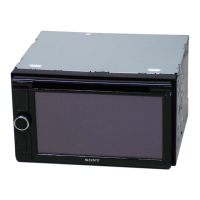
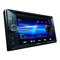
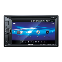
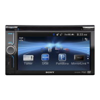
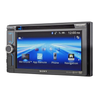
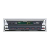
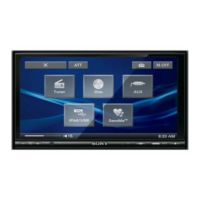
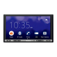
Identifies different unit versions based on region and view.

Unleaded Solder and Security Function

Info on unleaded solder characteristics and security function.

Important Repair and Replacement Notes

Notes on component replacement, board exchange, and connector notes.

Destination Setting Procedure

Step-by-step guide for setting destination after main board replacement.

Component Handling and Cleaning

Notes on flexible board handling, battery replacement, and connector cleaning.

GENERAL

Installation Cautions and Guidelines

General warnings and advice for unit installation and operation.

Wiring and Connection Diagrams

Diagrams illustrating wire settings and connections.

Power Supply and Speaker Connection Notes

Specific notes on power supply lead and speaker connection.

HDMI/MHL Cable Connection

Guidance on securing HDMI/MHL connection cables.

DISASSEMBLY

Disassembly Flow Chart

Visual guide showing the sequence of disassembly steps.

Fuse and Cover Removal

Steps for removing the fuse and cover.

DVD Mechanism Deck Removal

Procedure for removing the DVD mechanism deck.

Back Shield, Bracket, and IF Board Removal

Steps for removing back shield, bracket, and IF board.

Connector Assy, EXT-NAVI, and Bracket Removal

Procedures for removing connector assy, EXT-NAVI board, and bracket.

Connection Cord, Main Board, and DC Fan Removal

Steps for removing connection cord, main board, and DC fan.

Panel, D-SUB6, and KEY6 Board Removal

Procedures for removing panel, D-SUB6 board, and KEY6 board.

Chassis, Display Board, and LCD/Touch Panel Removal

Steps for removing chassis, display board, and LCD/touch panel.

ELECTRICAL ADJUSTMENT

Monitor Section Notes

Notes regarding monitor section adjustments.

Flicker Adjustment Procedure

Detailed steps for adjusting NTSC and PAL flicker settings.

DIAGRAMS

Audio Section Block Diagram

Block diagram illustrating the audio signal path.

Video and Panel Section Block Diagrams

Block diagrams for video and panel signal paths.

Power Supply Section Block Diagram

Block diagram showing the power supply circuitry.

Circuit Board Locations

Diagram showing the physical layout of circuit boards.

Printed Wiring Boards - Main Section (1/2)

Printed wiring board layout for the main section (part 1/2).

Printed Wiring Boards - Main Section (2/2)

Printed wiring board layout for the main section (part 2/2).

Schematic Diagrams - Main Section (1/4)

Schematic diagrams for the main section (part 1/4).

Schematic Diagrams - Main Section (2/4)

Schematic diagrams for the main section (part 2/4).

Schematic Diagrams - Main Section (3/4)

Schematic diagrams for the main section (part 3/4).

Schematic Diagrams - Main Section (4/4)

Schematic diagrams for the main section (part 4/4).

Printed Wiring Board - M-SUB6 Section

Printed wiring board layout for the M-SUB6 section.

Schematic Diagram - M-SUB6 Section

Schematic diagram for the M-SUB6 section.

Printed Wiring Board - D-SUB6 Section

Printed wiring board layout for the D-SUB6 section.

Schematic Diagram - D-SUB6 Section

Schematic diagram for the D-SUB6 section.

Printed Wiring Boards - External Terminal/Panel

Printed wiring boards for external terminal and panel sections.

Schematic Diagram - EXT-NAVI Board

Schematic diagram for the EXT-NAVI board.

Schematic Diagram - Panel Section

Schematic diagram for the panel section.

IC Block Diagrams

Block diagrams for various integrated circuits.

IC Pin Function Descriptions

Details on pin functions for specific ICs.

EXPLODED VIEWS

Overall Section Exploded View

Exploded view of the entire unit assembly.

Front Panel Section Exploded View

Exploded view of the front panel components.

Sub Panel Section Exploded View

Exploded view of the sub panel components.

IF Board Section Exploded View

Exploded view of the IF board components.

Chassis Section Exploded View

Exploded view of the chassis components.

Main Board Section Exploded View

Exploded view of the main board components.

ELECTRICAL PARTS LIST

Display, D-SUB6, and EXT-NAVI Parts

List of electrical parts for display, D-SUB6, and EXT-NAVI boards.

Main Board and M-SUB6 Parts List

List of electrical parts for the main board and M-SUB6 board.

Main Board Capacitors

Detailed list of capacitors used on the main board.

Main Board Resistors and Components

List of resistors and other components on the main board.

Main Board Components and M-SUB6 Parts

List of main board components and M-SUB6 parts.

Main Board Resistors and Components

List of resistors and other components on the main board.

Main Board Resistors and Components

List of resistors and other components on the main board.

Main Board and M-SUB6 Resistors/Components

List of main board and M-SUB6 resistors and components.

Related product manuals