Do you have a question about the Sony XBR-65X950B and is the answer not in the manual?
General instructions for qualified service personnel and safe operation.
Warnings regarding electric shock and the use of isolation transformers.
Importance of replacing critical safety components with specified part numbers.
Prohibits component-level repair of power supply and inverter boards.
Caution for lithium battery replacement to prevent explosion.
Essential safety checks to perform before returning the TV to the customer.
Procedures for measuring AC leakage current from exposed metal parts.
Method to verify the earth ground connection of an AC outlet box.
Detailed technical specifications for the TV model.
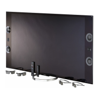
List of standard accessories provided with the TV.
Diagram illustrating the internal layout of the TV's main circuit boards.
Visual representation of the Smart Core block and its primary components.
Diagram showing internal cable routing and wire management.
Detailed illustration of the Smart Core block's components.
Steps to diagnose potential errors before servicing the television.
Procedure to access and interpret the TV's self-check diagnosis history.
A chart to help identify potential causes of errors based on symptoms.
A block diagram illustrating the TV's overall system architecture and signal flow.
Diagram detailing the power supply and control signal pathways within the TV.
Flowchart to diagnose and resolve issues where the TV does not power on.
Flowchart to diagnose problems indicated by standby LED blinking patterns.
Flowchart to diagnose and resolve issues related to no video display.
Flowchart to diagnose and resolve problems causing video distortion.
Flowchart to diagnose and resolve issues with the 3D viewing feature.
General steps and guidelines for performing TV repairs.
Step-by-step instructions for removing the table-top stand.
Detailed instructions on how to remove the rear cover of the TV.
Procedure for replacing the main board and tuner board.
Instructions for updating software and entering service mode after repairs.
Steps to set the serial number and variable types in the service menu.
Procedure to clear self-check error logs and replace power supply boards.
Instructions for replacing the switch unit and USB assembly.
Detailed steps for the physical removal of the Smart Core block.
Exploded diagram and part numbers for the table-top stand.
Exploded diagram and part numbers for the TV's rear panel components.
Exploded diagram and part numbers for internal brackets and speakers.
Exploded diagram and part numbers for VESA brackets and power boards.
Exploded diagram and part numbers for main, tuner, and KO boards.
Exploded diagram and part numbers for Smart Core block components.
Diagram identifying internal connectors and their part numbers.
List of screws used in the TV, with part numbers and applications.
List of standard accessories included with the TV.
Listing of various miscellaneous parts and their identification.
Information on optional accessories available for purchase.
Part numbers and identification for different remote commander models.
Guidelines for handling, repair, and destruction of confidential encryption key components.






 Loading...