7
Overview
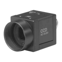
VIDEO OUT/DC IN/SYNC connector pin assignment
Pin No. Camera sync output External Sync (HD/VD) Restart/Reset External trigger shutter
1 Ground Ground Ground Ground
2 +12 V DC +12 V DC +12 V DC +12 V DC
3 Video output (Ground) Video output (Ground) Video output (Ground) Video output (Ground)
4 Video output (Signal) Video output (Signal) Video output (Signal) Video output (Signal)
5 HD output (Ground) HD input (Ground) HD input (Ground) HD input (Ground)
6 HD output (Signal) HD input (Signal) HD input (Signal) HD input (Signal)
7 VD output (Signal) VD input (Signal) Reset (Signal) VD input (Signal)
8————
9————
10 — — — WEN output (Signal)
11 — — — Trigger pulse input (Signal)
12 VD output (Ground) VD input (Ground) Reset (Ground) VD input (Ground)
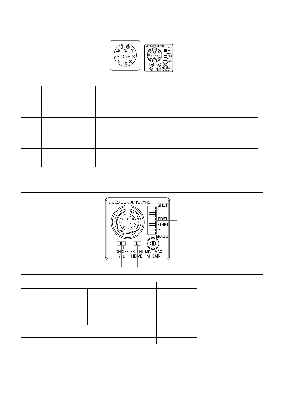
Rear panel
Factory setting mode of rear panel
Number Switch name Factory-setting mode
Shutter speed (bits 1–4) OFF
Potential accumulation mode (bit 5) FRAME
1
Shutter speed/ Restart reset/External trigger shutter
Normal
Mode setting DIP switch mode switch (bits 6–8)
γ
compensation ON/OFF switch (bit 9) OFF
GAIN switch (bit 0) MGC
2 Manual GAIN (M GAIN) control knob twelve o’clock position*
3 HD/VD signal input/output switch EXT
4 75 Ω termination switch ON
* When the GAIN switch is set to “MGC” (Manual), you can change the gain level in a range from 0 to 18 dB.
1
243