EasyManua.ls Logo

Sony XR-C550RDS User Manual

Sony XR-C550RDS
48 pages
To Next Page IconTo Next Page
Page #1 background imageLoading...
Page #1 background image
XR-C550RDS
AEP Model
UK Model
SERVICE MANUAL
SPECIFICATIONS
Model Name Using Similar Mechanism NEW
Tape Transport Mechanism Type
MG-25B-136
For RM-X2S (Remote Commander),
please refer to RM-X2S/X3S Service
Manual (9-960-039-) previously issued.
Dolby noise reduction manufactured under license
from Dolby Laboratories Licensing Corporation.
“DOLBY” and the double-D symbol a are trademarks
of Dolby Laboratories Licensing Corporation.
Ver 1.1 2001.06
9-925-544-12 Sony Corporation
2001F0500-1 e Vehicle Company
C 2001.6 Shinagawa Tec Service Manual Production Group
FM/MW/LW CASSETTE CAR STEREO
w
w
w
.
x
i
a
o
y
u
1
6
3
.
c
o
m
Q
Q
3
7
6
3
1
5
1
5
0
9
9
2
8
9
4
2
9
8
T
E
L
1
3
9
4
2
2
9
6
5
1
3
9
9
2
8
9
4
2
9
8
0
5
1
5
1
3
6
7
3
Q
Q
TEL 13942296513 QQ 376315150 892498299
http://www.xiaoyu163.com
2007.05.11
QQ :376315150
手机:13942296513
Question and Answer IconNeed help?

Do you have a question about the Sony XR-C550RDS and is the answer not in the manual?

Sony XR-C550RDS Specifications

General IconGeneral
RDSYes
CD PlaybackYes
WMA PlaybackNo
USB PortNo
BluetoothNo
Display TypeLCD
Chassis Type1 DIN
Tuner BandsFM
SecurityDetachable Front Panel

Summary

XR-C550RDS Service Manual

Specifications

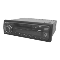
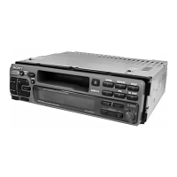
Overall product details and technical data.

Servicing Notes

Repairing Notes

Guidance for circuit board and chip component repair.

Section 1 General

Controls and Settings

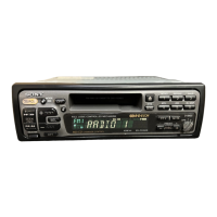
Location of controls and clock setting.

Other Functions

Remote Operation and Sound Adjustments

Using remote, sound, and muting functions.

Installation

Installation Procedures and Notes

Precautions, panel handling, mounting, and connection advice.

Connections

Power and Reset Operations

Power switch, reset, and control function notes.

Connection Diagram

Connection Examples and Notes

Illustrates wiring setups with explanations.

Power Connection

Wiring Warnings and Examples

Safety advice and wiring configurations.

Section 2 Disassembly

Unit Disassembly Steps

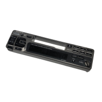
Procedures for front panel and cover removal.

Sub Panel and Mechanism Deck

Main Board and Heat Sink Removal

Steps for removing main board and heat sink.

Section 3 Mechanism Deck Assembly

Housing and Arm Assembly

Steps for assembling housing and arm components.

Lever and Gear Assembly

Lever and Gear Installation

Steps for assembling levers and gears.

Section 4 Mechanical Adjustments

Torque and Tension Measurements

Procedures for measuring mechanical forces.

Section 5 Electrical Adjustments

Test Mode Setup

Procedure to enter the test mode.

Tape Deck Section Adjustments

Tape Speed and Dolby Level Calibration

Procedures for tape deck performance tuning.

Tuner Section Adjustments

FM Auto Scan/Stop Level Adjustment

Procedure for FM scan level.

FM Stereo Separation Adjustment

FM Signal Meter Adjustment

FM Noise Focus Adjustment

AM (MW) Auto Scan/Stop Level Adjustment

Adjustment Location Guide

Component Location Views

Visual guide for adjustment points on the unit and board.

IC Block Diagrams - Main Section

IC1 and IC3 Block Diagrams

Functional diagrams for main section ICs.

IC Block Diagrams

IC151 and IC351 Block Diagrams

Functional diagrams for other ICs.

Waveforms

IC Waveform Characteristics

Signal characteristics for specific IC outputs.

Printed Wiring Boards - Main Section

Schematic Diagram - Main Section

Schematic Diagram - Main Board (1/3)

Schematic Diagram - Main Board (2/3)

Printed Wiring Board - Display Section

Schematic Diagram - Display Section

IC Pin Function Description

Main Board IC501 Pinout

Pin details for the system controller IC.

Section 7 Exploded Views

Chassis Section Exploded View

Visual breakdown of the chassis parts.

Front Panel Section

Mechanism Deck Section

Section 8 Electrical Parts List

Main Parts List Categories (Page 31)

Capacitors, Connectors, Jacks, Discharge Gap, Diodes, ICs

Lists of various electronic components.

Main Parts List Categories (Page 32)

Connectors, Jacks, Diodes, ICs

Lists of various electronic components.

Main Parts List Categories (Page 33)

Capacitors

List of capacitors.

Main Parts List Categories (Page 34)

Resistors

List of resistors.

Main Parts List Categories (Page 35)

Main Parts List Categories (Page 36)

Installation and Connection Parts

List of installation parts.

Supplement-1

Main Board Modification

Details on a main board change.

Diagrams Information

Notes on Diagram Conventions

Explains symbols and notations in diagrams.

Printed Wiring Board - Main

Schematic Diagram - Main Board (1/3)

Schematic Diagram - Main Board (2/3)

Schematic Diagram - Main Board (3/3)

Electrical Parts List (Page 43)

Capacitors

List of capacitors.

Electrical Parts List (Page 44)

Connectors, Jacks, Gaps, Diodes, ICs

Lists of various electronic components.

Electrical Parts List (Page 45)

Jacks, Chip Conductors, Coils, Transistors, Resistors

Lists of various electronic components.

Electrical Parts List (Page 46)

Resistors

List of resistors.

Electrical Parts List (Page 47)

Variable Resistors, Switches, Tuner Units, Vibrators

Lists of various components and items.

Revision History

Related product manuals