Page 13 / 22
Assembly instructions
Compact-Line kit
www.sorotec.de V 2.1.0
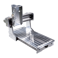
• Equip linear rails
16
/
17
from above with
cylinder screws
C3
and screw on slot 8 hammer
nuts
H1
below.
• Place the linear rails on the proles of the
portal beam
33
in such a way that the reference
edges of the linear guides marked with arrows
point to the milled stop edges (see Figure 10).
• Center the linear rails on the proles and
slightly counter-tighten the screws to turn the
hammer nuts by 90° in the T-slot.
• Screw the linear rails to the proles; the
reference edges of the linear guides must lie
against the milled stop edges of the proles
along their entire length. Tightening torque: 6 Nm
• Insert the sealing plugs into the holes in the
guide rails. Make sure they sit ush.
Fig. 10: Reference edges of the linear rails
17
16
33
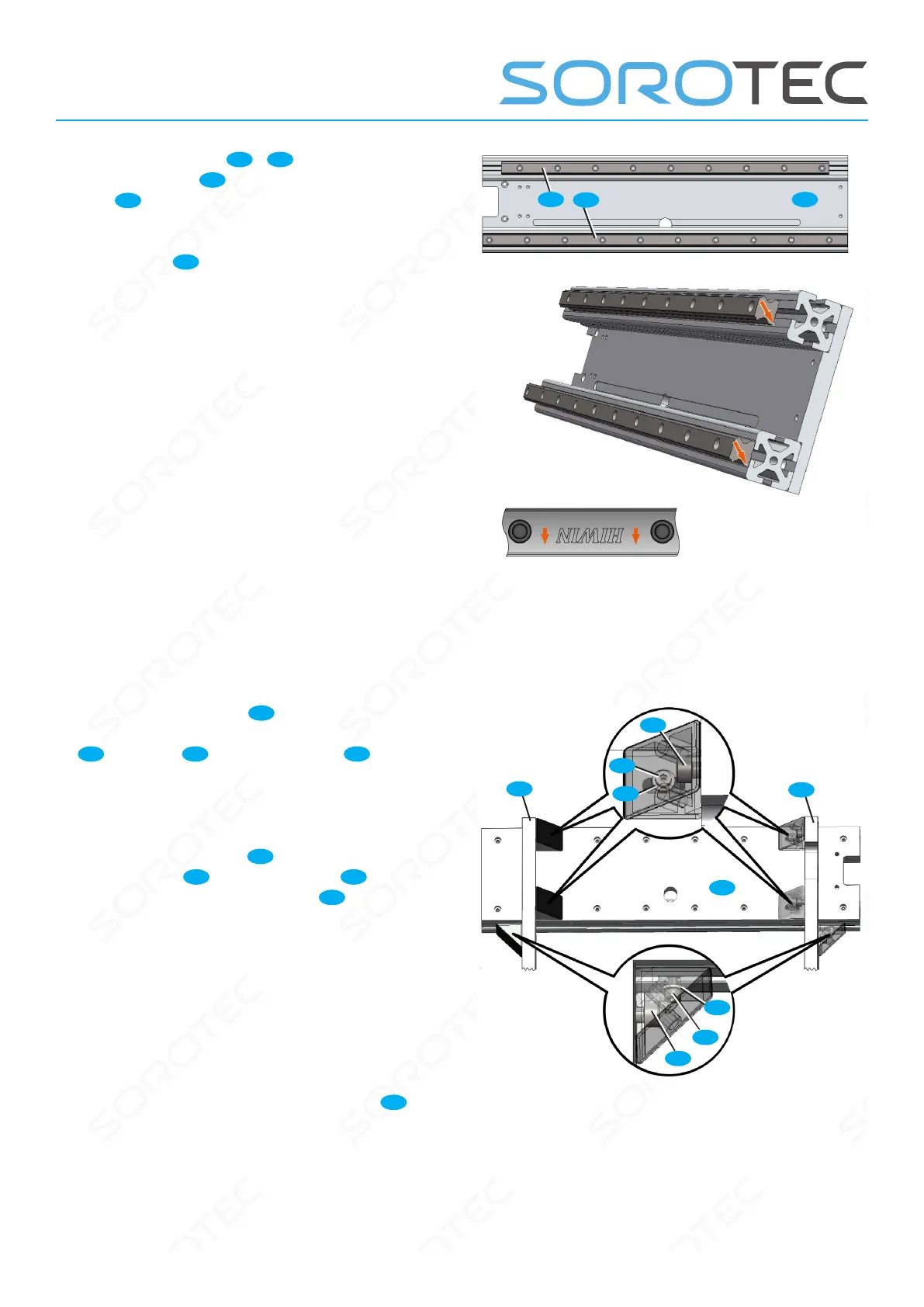
• Screw two brackets
31
to the lower prole of
the portal beam with cylinder head screws M5x16
C2
washers
W
and T-nuts slot 8
H1
(magnifying glass below in picture 11); Slightly
counter-tighten the screws so that the angles can
still just be moved on the prole.
• Equip four brackets
31
with one cylinder
screw M5x25
C5
and one washer
W
each and
loosely screw on a hammer nut
H1
lat the back.
• Insert hammer nuts through the slot on the
back of the portal beam into the prole and screw
the angle (magnifying glass above in picture 11);
Slightly counter-tighten the screws so that the
angles can still just be moved.
• Place the portal beam on the two portal walls
as shown in Figure 11 and screw all angles to the
portal walls with cylinder screws M8x16
D1
;
Slightly counter-tighten the screws
Fig. 11: Installation of the portal beam on the portal cheeks
C5
D1
C2
W
W
33
23l
23r
E1
 Loading...