Page 12 / 22
Assembly instructions
Compact-Line kit
www.sorotec.de V 2.1.0
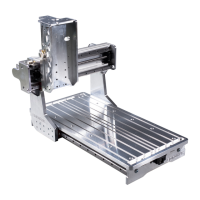
Assembly Y axis
Fig. 8: Portal and Y axis
9
2
5
14
17
16
23l
23r
33
1
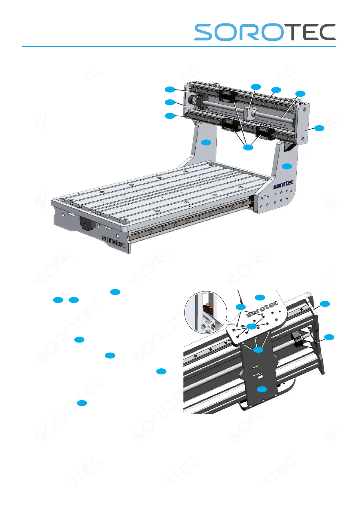
• Drive the cylindrical pins
Z
into the portal
cheeks
23l
/
23r
until they protrude 3 ... 4 mm on
the inside (see magnied picture 9).
• Place the portal panels with the cylinder pins
on the carriages and screw tight with cylinder
screws M5x20
C4
. Tightening torque: 6 Nm
• Insert the gantry beam
22
into the recesses of
the gantry stringers as shown in Figure 9 and
screw in place with cylinder screws M6x16
E1
;
Slightly counter-tighten the screws.
• Degrease the surfaces to be glued and stick
one rubber pad
12
to the front and one to the
rear of the front panel (not shown).
Fig. 9: Installation of portal stringers and beam
28
C4
E1
22
23r
12
Z
 Loading...