Page 15 / 22
Assembly instructions
Compact-Line kit
www.sorotec.de V 2.1.0
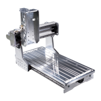
• Move the gantry forward as far as possible by
turning the ball screw
4s
(red arrows in Fig. 14).
• Tighten the oating bearing
4l
mounting
screws
E3
. Tightening torque: 10 Nm.
• Tighten the retaining screws
C4
of the
recirculating ball nut
4k
on the ange bracket X
8
. Tightening torque: 6 Nm.
• Carefully tighten the fastening screws
C3
of
the ange bracket X on the beam.
Fig. 14: Tightening the X-spindle screw connections
E3
4s
4l
C3
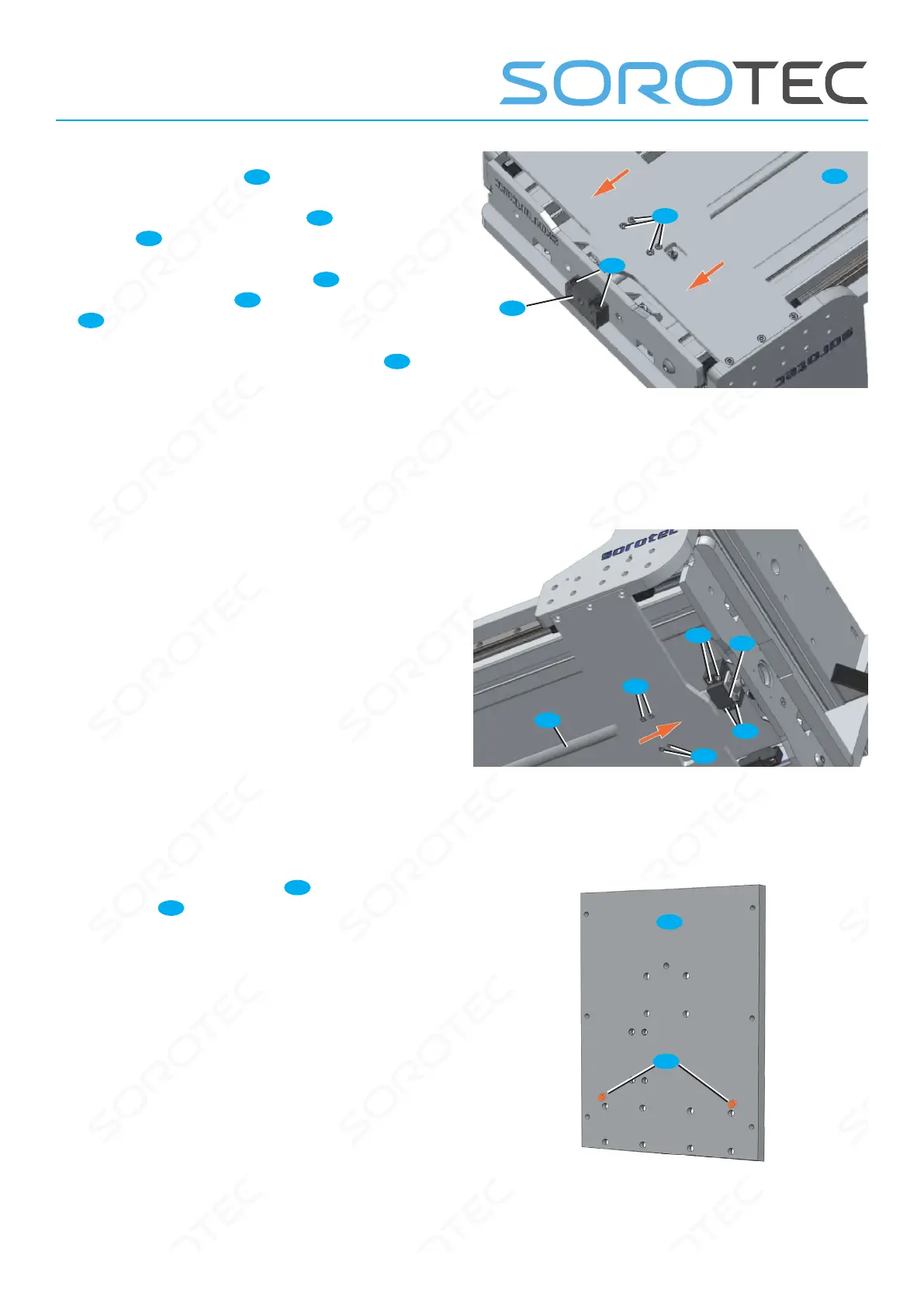
• Move the gantry backwards by turning the ball
screw (red arrow in Figure 15) until the fastening
screws of the xed bearing are just accessible.
• Tighten the xed bearing mounting screws.
Tightening torque: 10 Nm
Fig. 15: Tightening the X spindle xed bearing
C3
E3
E3
C3
4f
4s
• Drive the cylindrical pins
Z
from the back into
the sled Y
27
until they protrude by about
3 ... 4 mm.
Fig. 16: Cylindrical pins in sled Y
Z
27
 Loading...