Page 16 / 22
Assembly instructions
Compact-Line kit
www.sorotec.de V 2.1.0
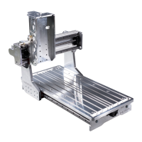
• Slide one carriage
14
onto the upper linear
rail
16
and two carriages
14
onto the lower
linear rail
17
; the following must be observed:
- Ground, blank surfaces on the long sides of
the carriage point upwards
- Equip the lower carriage with straight grease
nipples so that they point outwards (red
arrows below in Figure 17).
- Equip the upper carriage with a 45° grease
nipple so that it points upwards to the left (red
arrow above in Figure 17).
• Place sled Y
27
with the cylinder pins on the
lower carriage and screw with cylinder screws
M5x12
C1
verschrauben. Tightening torque:
6 Nm
• Screw carriage Y to the upper carriage; Slightly
counter-tighten the screws.
• Move carriage Y back and forth several times
as far as possible to the left and right on the
linear rails; while doing so, gradually tighten
the fastening screws of the upper carriage.
Tightening torque: 6 Nm
Fig. 17: Mounting sled Y on the portal
14
16
17
27
Z
14
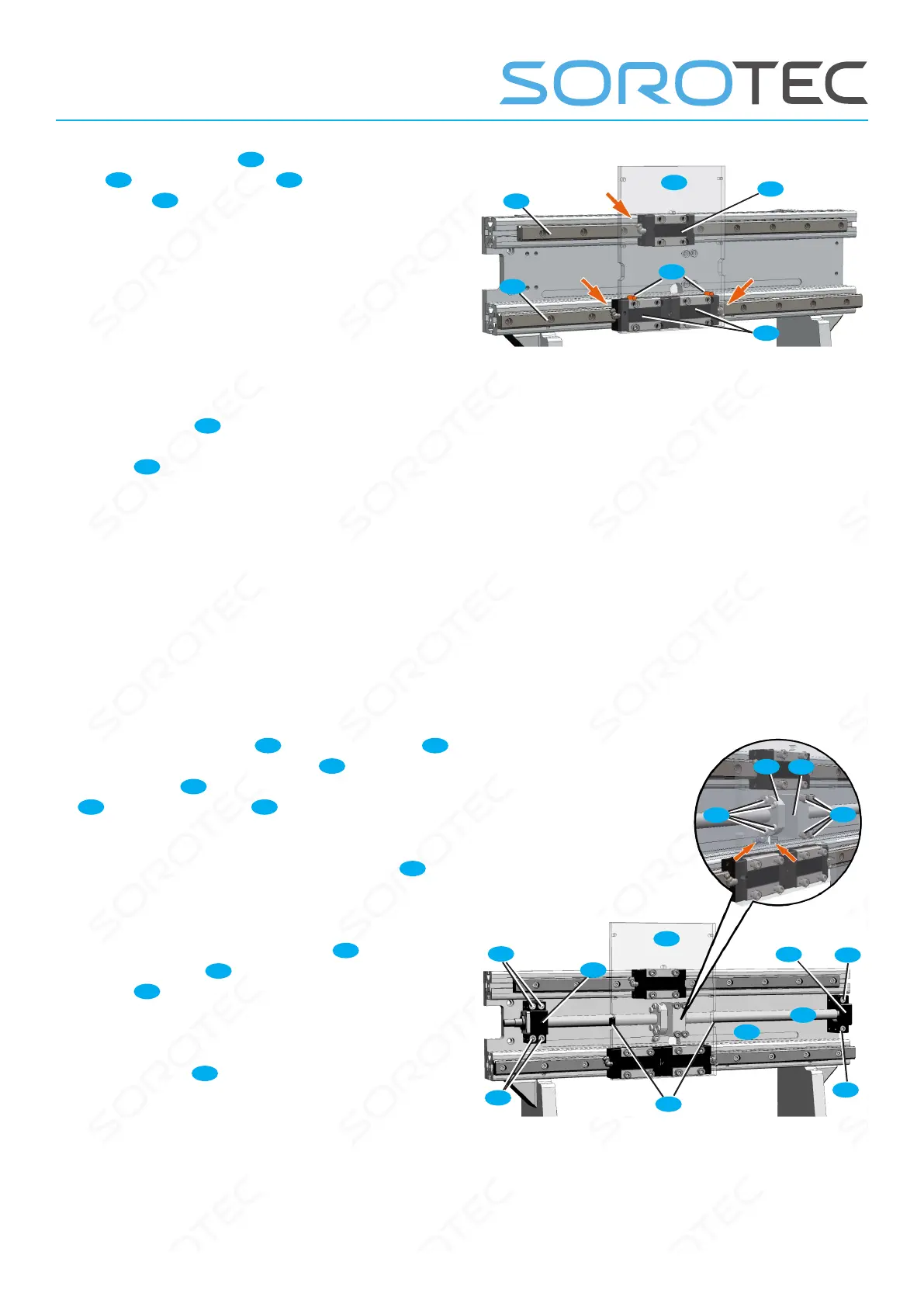
• Guide the ball screw
5s
behind the sled Y
27
as shown. Screw loose bearing
5l
with 2 and
xed bearing
5f
with 4 cylinder screws M6x40
E3
to the portal beam
33
; Slightly counter-
tighten the screws
• Tighten the grease tting on the ball nut
5k
sso that it faces the opening in the gantry beam
(red arrows in Figure 18).
• Screw the recirculating ball nut
5k
to the
ange bracket Y
9
musing cylinder screws
M5x20
C4
; Slightly counter-tighten the screws.
• Move sled Y so that the carriage can be
mounted to the ange block Y with cylinder
screws M5x16
C2
; Slightly counter-tighten the
screws.
• Move sled Y to the xed bearing by turning
the ball screw until the xing screws of the xed
bearing are just accessible.
Fig. 18: Installation of the Y spindle
C4
C2
5k
33
5f
5l
5s
27
12
9
E3
E3
E3
E3
 Loading...