Page 18 / 22
Assembly instructions
Compact-Line kit
www.sorotec.de V 2.1.0
Note
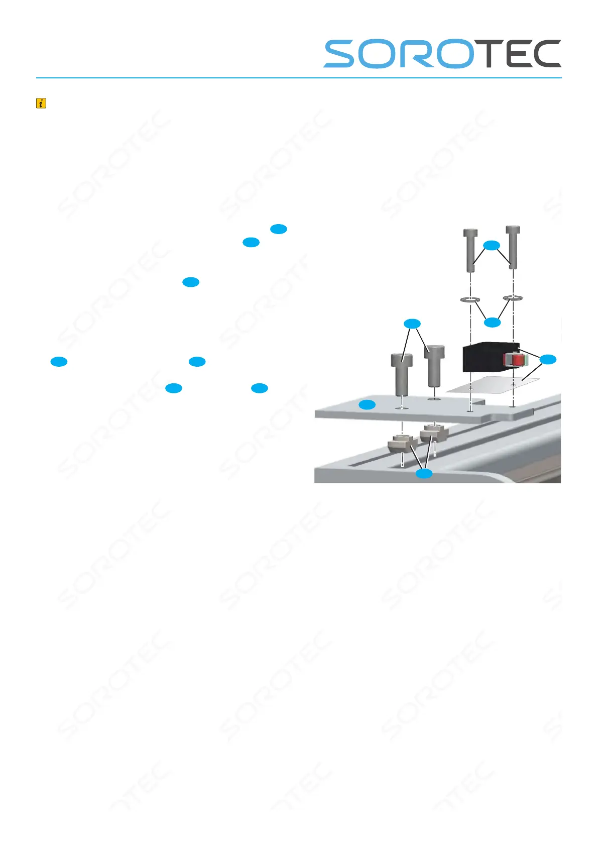
The switch carrier Y is mounted on the left out-
side on the prole of the portal beam. When
installing the reference switch, observe the addi-
tional instructions for the electrical installation kit,
if necessary.
Fig. 21: Mounting reference switch Y-axis
24
H1
C1
26
U
A1
• Equip the switch carrier Y with two screws
C1
and loosely screw on the hammer nuts
H1
at the
back.
• Position switch carrier Y
26
, threading
hammer nuts into the T-slot of the prole. To turn
the T-nuts 90° in the T-slot, tighten the screws
slightly.
• Place the shim between the reference switch
24
and the switch carrier Y
26
and screw it
ush with the outer edge of the prole using
cylinder screws M3x16
A1
and washers
U
.
 Loading...