Page 20 / 22
Assembly instructions
Compact-Line kit
www.sorotec.de V 2.1.0
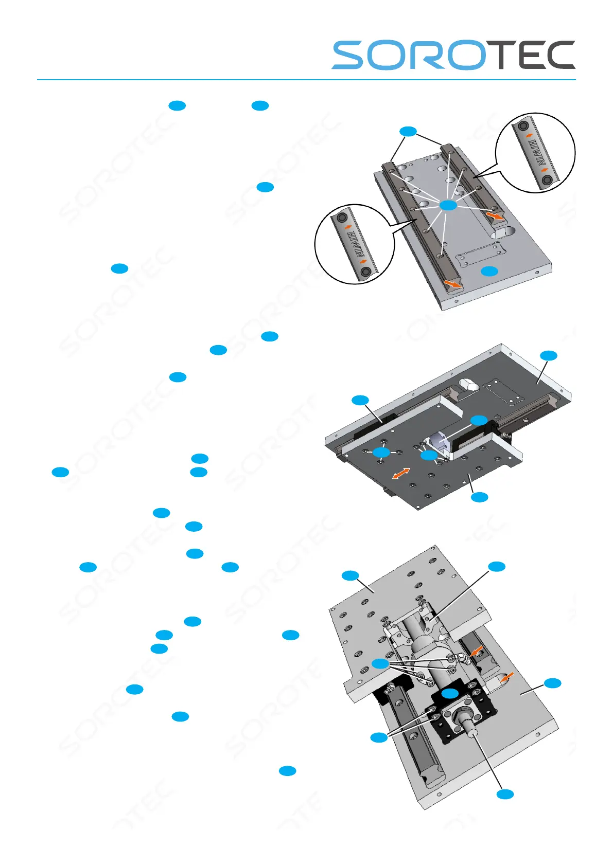
• Place the linear rails
18
on the plate
21
so
that the reference edges (above the „HIWIN“
lettering, see Figure 24) of the linear guides point
to the milled stop edges of the plate Z (red
arrows).
• Screw linear rails with cylinder screws
C4
;
Slightly counter-tighten the screws.
• Starting in the middle, tighten the screws
evenly outwards; the reference edges of the
linear rails must lie against the milled stop edges
of the plate
21
over their entire length.
Tightening torque: 6 Nm
• Seal the holes in the rails with plugs.
• Slide the carriages with the guide plate
11
onto the linear rails of the plate
21
.
• Slide the guide plate
21
back and forth
several times over the entire travel on the linear
rails; while doing so, gradually tighten the
fastening screws of each individual carriage.
Tightening torque: 6 Nm
• Screw the ange bracket
10
to the guide plate
11
cylinder screws M5x16
C2
; Slightly counter-
tighten the screws.
• Insert the spindle
6
with the recirculating ball
nut into the ange bracket
10
as shown.
• Put on the xed bearing
6f
and screw it to the
plate
21
with four screws M6x40
E3
; Slightly
counter-tighten the screws.
• Tighten the ball nut grease tting so that it
faces the hole in the plate
21
. Screw the
recirculating ball nut
6k
to the ange bracket
10
with M5x20 screws
C4
. Tightening torque: 6 Nm
• Carefully tighten the fastening screws on the
ange bracket
10
.
• Move the guide plate
11
as far as possible
towards the xed bearing by turning the ball
screw.
• Tighten the xed bearing mounting screws
6f
.
Tightening torque: 10 Nm
Fig. 24: Assembly of the linear rails
Fig. 25: Assembly of the guiding group
Fig. 26: Spindle grease tting towards port (red arrows)
21
C4
18
C2
14
10
11
21
C2
6
E3
C4
10
6f
11
21
 Loading...