Page 21 / 22
Assembly instructions
Compact-Line kit
www.sorotec.de V 2.1.0
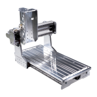
• Screw the pre-assembled Z-axis to the Y-sled
with M5x18 screws
C3
; Slightly counter-tighten
the screws.
To align the Z-axis, a dial indicator must be attached
to the plate
21
and a try square must be attached to
the table. Rotating the ball screw of the Z-axis moves
it up and down.
• Align the Z-axis so that the dial gauge does
not deect when moving up and down the Z-axis.
In this position, tighten the fastening screws.
Tightening torque: 6 Nm
Fig. 27: Aligning the Z axis on the machine
• Mount the stop plate
3
with M5x16 screws
C2
on the underside of the plate
21
; Slightly
counter-tighten the screws.
Fig. 28: Assembly of the stop plate
21
C2
3
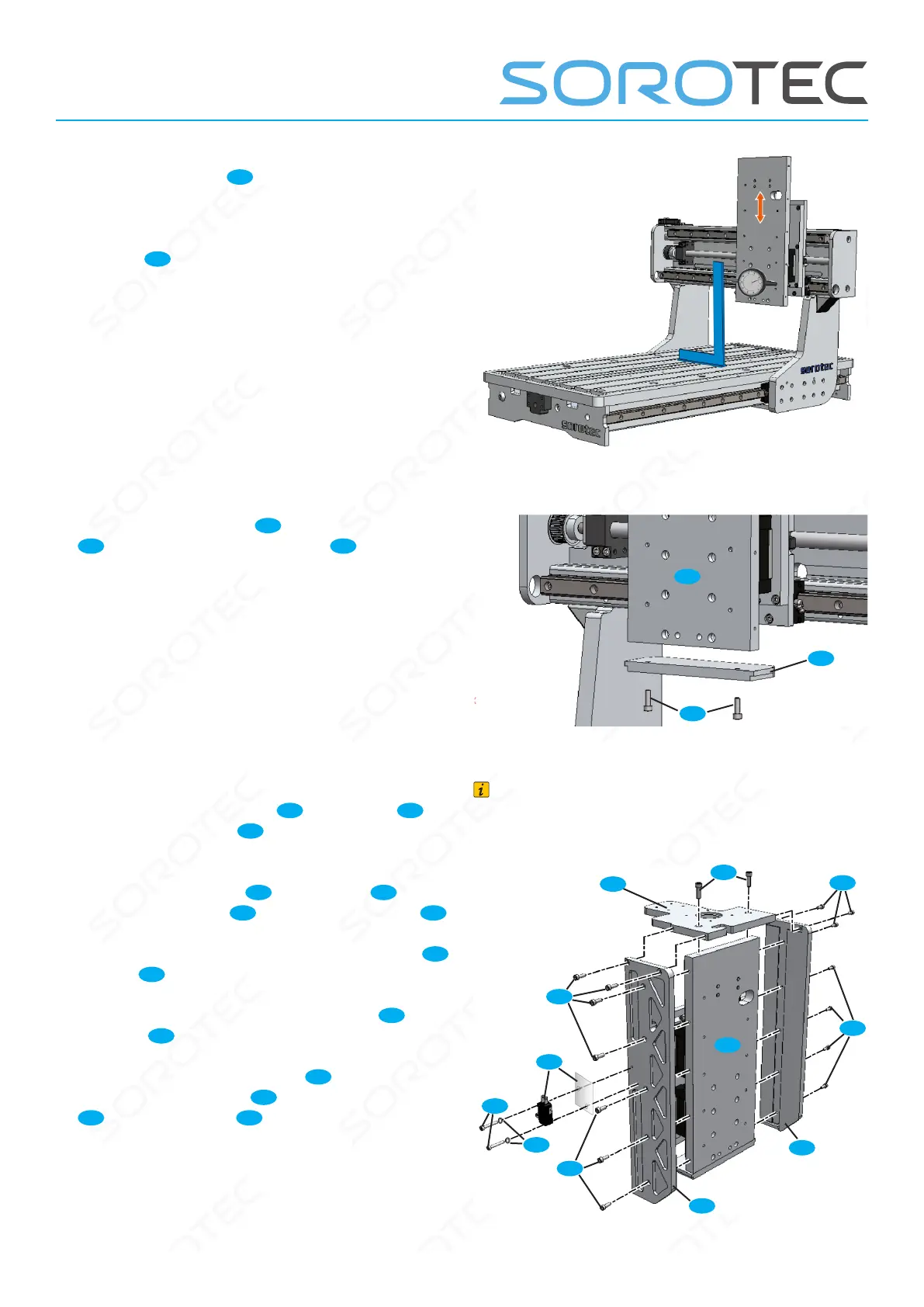
• Attach the motor ange
20
to the plate
21
using M5x16 screws
C2
; Slightly counter-tighten
the screws
• Mount the bracings
7
on the plate
21
and
on the motor ange
20
using M4x12 screws
B1
.
• Tighten the fastening screws (motor ange
20
to plate
21
).
• Tighten the fastening screws (braces
7
on
the plate
21
).
• Mount the reference switch
24
together with
the shim with washers
U
and M3x16 screws
A1
on the left brace
7l
.
Note
In the following gure, only the Z-axis is shown
for a better overview.
Fig. 29: Assembly of motor ange and stieners
B1
A1
B1
20
C2
21
7l
7r
B1
B1
24
U
 Loading...