4. Install the SOS 12 unit—see SOS 12 installing instrucons
5. Run a two wires 18—22 AWG stranded (not included) from the terminal strip on the Re-
mote Mic to the terminal strip on the SOS 12 board. Do not exceed 50 feet.
6. Unplug the microphone from the SOS 12 board.
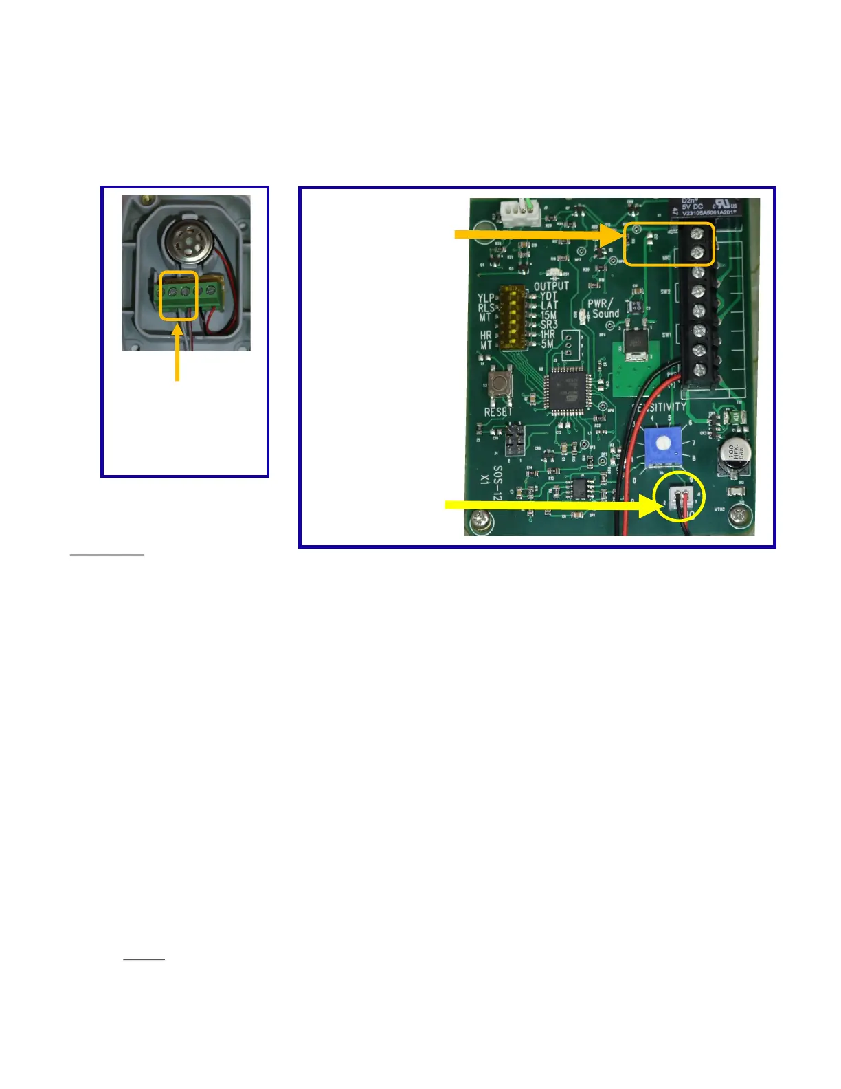
Remote Mic
Connect wires
from here to
SOS 12 board
SOS 12 Board
Unplug the
microphone here
Connect wires
from remote
mic here
TEST UNIT
7. Begin tesng by turning the sensivity dial clockwise to seng 8.5.
8. Using the Yelp Siren CD provided, or download the MP3 yelp o our website www.sosgate.com
onto your mobile device, play it at the loudest volume seng. Hold your device close to the mi-
crophone, the PWR/Sound light should come on solid, and the output light should come on as the
gate opens within 3 seconds.
9. Test the unit now with a live siren. You want to have the sensivity seng as low as possible,
but sll able to open the gate with a live siren. The main reason for the SOS not triggering the
gate open is, that they are using a dierent siren sound than “YELP” or they are only leaving their
siren on for 1-2 seconds.
10. Have the emergency responder sound their “YELP” siren. If the gate does not open within 3
seconds, verify that the PWR/Sound light is coming on solid. If PWR/Sound light is solid and the
gate sll does not open turn up the sensivity. The output light must come on before an open
trigger is sent to the gate operator.
Note: Every me the siren is interrupted or changed the digital processor begins the
process over again, this internal reset can take several seconds.
702 Faireld St. W. • Twin Falls, ID 83301 • (800) 767-4283 • (208) 734-0467
 Loading...