EasyManua.ls Logo

Soundoff Signal nROADS - User Manual

Default Icon
14 pages
Print Icon
To Next Page IconTo Next Page
Loading...
nROADS Lightbar_Single Color - English 08201.
LED Lightbar - Single Color
TABLE OF CONTENTS
PAGE CONTENT
1 COMPONENTS/ CONTENTS
2 MODULE SPECIFICATIONS
3 TECHNICAL/ POWER SPECIFICATIONS
4 FIXED HEIGHT BRACKETS AND HOOK MOUNTING
5 GASKET MOUNTING & WIRE SLEEVE
INSTRUCTIONS
6 INPUT WIRE DEFINITIONS
7-10 ELECTRICAL INSTALLATION
11 LIGHT MODULE REPLACEMENT
12 nROADS TROUBLESHOOTING
13 REPLACEMENT PARTS
14 WARRANTY AND RETURN GOODS PROCEDURE
• Warning devices are strictly regulated and governed by Federal, State
and Municipal ordinances. These devices shall be used ONLY on approved
vehicles. It is the sole responsibility of the user of these devices to ensure
compliance.
• DO NOT install this product or route any wires in the Air Bag Deployment
Zone. Refer to your vehicle Owner’s Manual for the location of any air
bag deployment zones.
• DO NOT connect this device to a strobe power supply. This product is
self-contained and does not require an external power supply.
Important Information:
!
WARNING
This product contains high intensity LED devices. To
prevent eye damage, DO NOT stare into the light
beam at close range.
IMPORTANT NOTICE TO INSTALLER: Make sure to read and understand
all instructions and warnings before proceeding with the installation of this
product. Ensure that the manual and any warning cards are delivered to the
end user of this equipment. Proper installation of the lightbar requires the
installer to have a thorough knowledge of automotive electronics, systems,
and procedures. Lightbars provide an essential function of an effective visual
warning system. The use of the lightbar does not ensure that all drivers can
or will abide by or react to an emergency warning signal, especially at high
rates of speeds or long distances. The operator of the vehicle must never take
the right of way for granted and it is the operator’s responsibility to proceed
safely. The effectiveness of the lightbar is highly dependant on the correct
mounting and wiring. The installer must read and follow the manufacturer’s
installation instructions and warnings in the manual. The vehicle operator
should verify daily that the lightbar is securely fastened to the vehicle and
properly functioning before operating vehicle. The lightbar is intended for use
by authorized personnel only. It is the user’s responsibility to ensure they
understand and operate the emergency warning devices in compliance with
the applicable local, state and federal laws and regulations. SoundOff Signal
assumes no liability for any loss resulting from the use of this warning device.
Components/Contents
Standard Equipment:
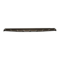
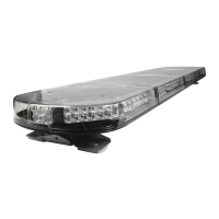
1 - nROADS® Fleet LED Lightbar built to your specications
Other Parts that may be included depending on your conguration:
1 - Vehicle Specic Hook Kit w/ Hardware*
2 - Fixed Height Mounting Brackets w/ Hardware or
1 - Flat Mount Hardware Kit or
2 - Headache Brackets w/ Hardware
*Kits will vary with each lightbar depending on vehicle specied on order form.
Unpack Lightbar
1. Remove the lightbar from box and packaging.
2. Save packaging for later shipping.
3. Check components/contents.
4. Please reference these instructions for proper wiring and installation.
Tools Required for Installation
• 7/16“ Socket with ratchet
• Phillips Head Screwdriver
• Drill bit #30
A A
B B
C C
D D
E E
F F
G G
9
9
8
8
7
7
6
6
5
5
4
4
3
3
2
2
1
1
CAD DIMENSIONS ARE BASIC
UNLESS OTHERWISE SPECIFIED
GD&T TO FOLLOW
ASME Y14.5M-1994
DRAWING NO:
B
PRIMARY DIMS:
INCH
DUAL DIMS: [mm]
TOLERANCES
EXCEPT AS NOTED
.X ± .020
.XX ± .012
.XXX ± .006
ANGLES ± .5°
DO NOT SCALE
DRAWING
SIZE:
SHEET
1 OF 3
DESCRIPTION:
REVISION:
®
PROPRIETARY AND CONFIDENTIAL
THE INFORMATION CONTAINED IN
THIS DRAWING IS THE SOLE
PROPERTY OF SOUNDOFF SIGNAL.
ANY REPRODUCTION IN PART OR
AS A WHOLE WITHOUT THE
WRITTEN PERMISSION OF
SOUNDOFF SIGNAL IS PROHIBITED.
THIRD ANGLE
PROJECTION
MESA LIGHT BAR ASSEMBLY
MATERIAL:
MESA_LIGHT_BAR_ASSEMBLY-INSTALL.SHEET.UPDATES
NOTICE:
Installers and users must comply with all applicable federal, state and local laws regarding use and installation of warning devices. Improper use or installation may void
warranty coverage. To review our Limited Warranty Statement & Return Policy for this or any SoundO Signal product, visit our website at www.soundosignal.com/sales-
support. If you have questions regarding this product, contact Technical Services, Monday - Friday, 8 a.m. to 5 p.m. or after hours 5 p.m. to 8 p.m. EST at 1.800.338.7337 (press
#4 to skip the automated message). Questions or comments that do not require immediate attention may be emailed to techservices@soundosignal.com.
SUPERIOR CUSTOMER RELATIONSHIPS. SMARTLY DESIGNED LIGHTING & ELECTRONIC SOLUTIONS.
1.800.338.7337 / www.soundo󰀨signal.com
Question and Answer IconNeed help?

Do you have a question about the Soundoff Signal nROADS and is the answer not in the manual?

Overview

The nROADS LED Lightbar is a single-color warning device designed for use on approved vehicles, providing an essential function for effective visual warning systems. It is intended for use by authorized personnel only, and users are responsible for ensuring compliance with applicable local, state, and federal laws and regulations. SoundOff Signal assumes no liability for any loss resulting from the use of this warning device.

Function Description:

The lightbar provides various flashing and steady-on patterns for warning, takedown, and directional arrow functions. It can be configured with different LED modules, including inboard, corner, takedown, and integrated alley light modules, to meet specific vehicle warning requirements. The directional controller is built-in with arrow patterns for left, right, and center-out arrows.

Important Technical Specifications:

  • Material: Aluminum Base, polycarbonate outer lenses, ASA/PC top cover.
  • Roof Attachments: 1/4" bolt Stainless A2.
  • Operating Temperature: -40° to +65° C.
  • Input Voltage Range: 10-16Vdc.
  • Standby Current: <0.10 mA.
  • Reverse Polarity: Protected.
  • Load Dump: Protected.
  • Wiring: Power Cable: 15ft, 16 AWG Wires, (+) Red, (-) Black. Control Cable: 8 or 12 wire, 8 or 12 Conductor STT Cable: 15ft, 22AWG, 4 Conductor.
  • Power Consumption (Typical): 14 mW.

Module Specifications (at 12.8Vdc):

  • 6 LED Single Color Inboard Module: 0.2 Amps (Flashing) / 0.4 Amps (Steady On), 2.6W (Flashing) / 5.2W (Steady On).
  • 9 LED Single Color Inboard Module: 0.3 Amps (Flashing) / 0.6 Amps (Steady On), 3.9W (Flashing) / 7.8W (Steady On).
  • 6 LED White Takedown Module: 0.2 Amps (Flashing) / 0.4 Amps (Steady On), 2.6W (Flashing) / 5.2W (Steady On).
  • 9 LED Single Color Corner Module: 0.3 Amps (Flashing) / 0.6 Amps (Steady On), 3.9W (Flashing) / 7.8W (Steady On).
  • 12 LED Single Color Corner Module: 0.4 Amps (Flashing) / 0.8 Amps (Steady On), 5.2W (Flashing) / 10.4W (Steady On).
  • 18 LED Single Corner Module: 0.6 Amps (Flashing), 7.8W (Flashing).
  • Corner Module with Integrated Alley Light Module: 0.25 Amps (Flashing) / 0.5 Amps (Steady On), 3.2W (Flashing) / 6.4W (Steady On).

Usage Features:

  • Installation: Requires thorough knowledge of automotive electronics. Mounting options include fixed height brackets, hook mounting, and gasket mounting. Wires must be routed carefully, avoiding air bag deployment zones and areas subject to potential wear. A 10 Amp fuse (customer supplied) must be installed on the RED power wire.
  • Control: The lightbar connects to switches capable of providing +12V at a minimum of 1mA to the 8 or 12 control wire harness.
  • Cruise Mode: Allows programming selected lights to "glow" when activated.
  • Directional Arrow Built-in: Provides left, right, and center-out arrow patterns. Requires the 12-wire control harness.
  • Scene Light Mode: Allows programming selected lights to turn steady on for additional scene lighting. Requires the 12-wire control harness.
  • Stop/Tail/Turn Mode: If equipped with STT modules, separate control wires control stop, tail, left turn, and right turn functions.
  • Low Power Mode: Operates lighting at reduced intensity.
  • Standby Mode: A very low power mode that extends battery life when no active inputs are present. The lightbar awakens when any input is activated.
  • Flash Pattern Configuration: Patterns can be changed by momentarily connecting the Pattern Select wire to GND for defined amounts of time. The lightbar will flash "10s" on the left and "1s" on the right corner modules to indicate the pattern number.
  • Arrow Flash Pattern Configuration: Similar to flash patterns, arrow patterns can be configured by momentarily connecting the Pattern Select wire to GND.
  • Takedown and Work-Light Configuration: Takedown and work-light settings can be changed by momentarily connecting the Pattern Select wire to GND.
  • Cruise Mode Set-Up: Cruise mode settings can be changed by momentarily connecting the Pattern Select wire to GND.
  • Replacement of Inboard and Corner Modules: Modules can be replaced by removing the top cover, disconnecting the module, and securing the new module.
  • Replacement of Controller Board: The controller board can be replaced by removing the top cover, disconnecting wire harnesses, and securing the new board. Dip switches on the controller board must be set correctly for the lightbar length.

Maintenance Features:

  • Cleaning: Clean lenses with mild soapy water and a soft cotton cloth. Avoid harsh chemicals or abrasive cleaners.
  • Mounting Integrity: Periodically check the integrity of all hardware/mounting bracket integrity to ensure secure attachment to the vehicle.
  • Daily Checks: The vehicle operator should verify daily that the lightbar is securely fastened and properly functioning.

Troubleshooting:

  • No Operation: Check input power and ground, signal wires for damage/opens, input power wire for minimum 10.0 Volts, and fuse.
  • No Takedown Lights: Verify configuration and ensure light modules are configured for takedown function.
  • No Light Operation in Only 1 Module: Verify module is not configured as a takedown/worklight that is not configured to flash with warning, check connection to module, and note that STT modules will not flash on Arrow.
  • Arrow Pattern Incorrect Length: Verify configured arrow length and correct lightbar length setting on Controller Dip Switches.

Warnings:

  • High intensity LED devices: DO NOT stare into the light beam at close range to prevent eye damage.
  • Wiring: DO NOT install or route wires in the Air Bag Deployment Zone. Refer to the vehicle owner's manual for airbag deployment zones.
  • Power Supply: DO NOT connect this device to a strobe power supply; it is self-contained.
  • Customer Supplied Power Wires: Must be sized to supply at least 125% of the maximum current and properly fused at the power source.
  • Cables: Insert grommet when passing cables through firewall or other sheetmetal to protect the cable.
  • Warning Devices: Strictly regulated by Federal, State, and Municipal ordinances. Use ONLY on approved vehicles.
  • Mounting: The lightbar must be securely mounted for safe operation. Monitor lightbar and roof deflection when torqueing bolts.

Warranty and Return Goods Procedure:

  • Warranty: SoundOff Signal products are covered by a limited warranty. Improper use or installation may void warranty coverage.
  • Return Process: Contact Technical Services for a Return Merchandise Authorization (RMA) number. RMA numbers are valid for 30 calendar days. Products must be shipped back in original packaging with the RMA number clearly marked.

Soundoff Signal nROADS Specifications

General IconGeneral
BrandSoundoff Signal
ModelnROADS
CategoryAutomobile Accessories
LanguageEnglish

Related product manuals