Do you have a question about the South ET-02 and is the answer not in the manual?
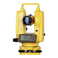
Details telescope, horizontal axis, handgrip, collimator, vertical axis, clamp units.
Outlines the components of the vertical clamp and tangent mechanism.
Describes the horizontal clamp and tangent mechanism.
Details leveling units, battery specs, optical plummet, display, and CCD.
Instructions for separating and cleaning the base and leveling screws.
Gather tools, prepare a tray, and record part details.
Explains the disassembly process for ET-02/ET-05 models.
Remove the left cover and disconnect the internal wiring.
Remove the angle main board and its connectors.
Remove the display plate and the LCD module.
Remove the right cover, taking care of power wires.
Remove dust-proof screws, CCD laser tube, and encoder disk unit.
Remove vertical CCD unit and other CCD units carefully.
Remove the fix cover of the horizontal axis sheath.
Loosen fix screws and manipulate the vertical clamp handwheel.
Remove tilt sensor plug and mounting screws.
Loosen horizontal clamp fix screws and move the component.
Separate the base, remove covers, and disconnect units.
Remove horizontal CCD units carefully after separating parts.
Separate main body from lower base, remove axis fix cover.
Loosen adjusting screw and remove the plate vial.
Loosen fix screws and gently remove the optical plummet.
Details on maintaining common faults like cover loose, circuit issues, sensor errors.
Addresses battery voltage, driver circuit, and mainboard issues.
Covers vertical axis blocking and initial adjustment steps.
Apply abrasive paste and grind axis shaft and sheath for smooth operation.
Mount bearings, reassemble vertical axis, and check for tightness.
Clean axis shaft and sheath using cotton.
Apply abrasive paste to grinding stick and grind axis shaft/sheath.
Labels and locations of various connectors on the main board.
Tools, handwashing, and overview of adjustment procedures.
Procedure for adjusting the plate level bubble to be centered.
Centering the circular bubble using adjustment screws.
Aligning the reticle with collimator crosshairs.
Measuring and correcting the angle between sight line and horizontal axis.
Adjusting horizontal clamp and tangent screw for difference.
Measuring and adjusting vertical crosshair alignment for high-low difference.
Adjusting the compensator frequency value (F value) within ±60.
Verifying F value is within ±60 and checking temperature coefficient.
Calculating and resetting compensator coefficient if F value is outside range.
Measuring vertical angle (V1, V2) and calculating the I angle.
Adjusting the instrument to meet the ±10 requirement for I angle.
Adjusting optical plummet focus and centering the mark.
Using correction pins to align optical plummet center mark.
Lists and shows images of necessary tools like oscilloscopes and screwdrivers.
Lists chemical supplies such as lubricants, alcohol, and grease.
| Brand | South |
|---|---|
| Model | ET-02 |
| Category | Measuring Instruments |
| Language | English |