Do you have a question about the South N6+ Series and is the answer not in the manual?
Measure and save angle data, including multiple round observations.
Measure and record distance, calculating target coordinates.
Set occupied point, view coordinates, and input instrument height/backsight.
Calculate distance elements (SD/HD/VD) for stakeout points.
Measure and save coordinates under current coordinate and measure files.
Create a new job, name it, and save measurement/coordinate data.
Input or call occupied point, set instrument height, and define backsight.
Orient backsight by coordinate or angle.
Set up station using angle and distance measurements from multiple points.
View file list to select data for stakeout operations.
Check guidance for direction, measure distance, and guide prism movement.
Create, import, export, rename, or delete measurement files.
Create, import, export, rename, or delete measurement files.
Transfer data between the N6+ and PC via Bluetooth or USB.
Connect N6+ to PC, send data, and load data.
Measure HD/VD/SD/HL/HR between two points (MLM-1, MLM-2).
Steps to calculate horizontal and vertical curves using N6+.
Input starting values and linear elements for horizontal curves.
Input starting point, slope, and ending point data for vertical curves.
Input occupied points, set STN/BS, and calculate/layout points.
Calculate pile numbers and coordinates using manual input or measurements.
Steps to calculate roads using N6+ for H curves.
Input starting value and linear elements for horizontal curves.
Calculate coordinates of vertical points from point 1-3.
Steps to calculate roads using N6+ for vertical curves.
Input starting value and linear elements for horizontal curves.
Input starting point, slope, and ending point data for vertical curves.
Calculate pile numbers and coordinates using manual input or measurements.
Calculate coordinates of extra piles behind/before/among short-chainage.
Steps to calculate roads using N6+ for H curves.
Input starting value and linear elements for horizontal curves.
Input starting/ending pile number and height for vertical curves.
Calculate coordinates of extra piles behind/after long-chainage.
Steps to calculate roads using N6 for residential roads.
Input starting value and linear elements for horizontal curves.
Perform inverse calculation for point P1.
Calculate coordinates of middle pile for layout points.
Perform V0, Collimation, Horizontal Axis, and V0/Axis Const adjustments.
Calculate and adjust vertical disk error.
| Brand | South |
|---|---|
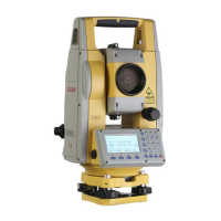
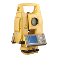
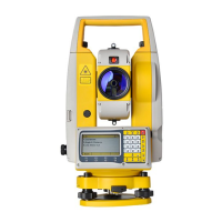
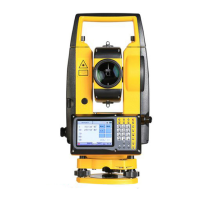
| Model | N6+ Series |
| Category | Measuring Instruments |
| Language | English |