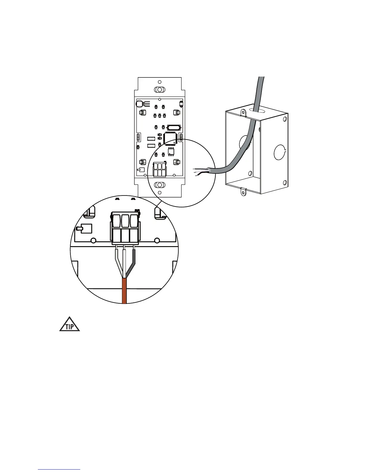
IV. PixiePlus Installation cont’d
3. Wire Controller
Connect the 3-conductor cable to the captive screw connector on the back of the
PixiePlus. Be sure that the wires match the connections on the cable assembly
block end - the PixiePlus uses crossover wiring.
Verify the captive screw connectors are fully open before inserting the wires.
It is possible to physically anchor the wires without making a solid electrical
connection if they are turned the wrong way.
BUS
+6V
GND
BUS
+6V
GND
Wire landing must match
landing on cable assembly
block at the display device
side (see pg. 4).
7