14
SHOCKER CVO
WWW.SHOCKERPAINTBALL.COM
15
PLEASE READ CAREFULLY PLEASE READ CAREFULLY
GRIP FRAME
Removal of the grip frame is an advanced maintenance
procedure that should only be performed when needed to repair
a leak or replace a damaged component.
RUBBER GRIP The wrap-around grip must be removed to make
some trigger adjustments, or to be replaced with custom grips.
This is achieved by using a 5/64-inch hex key. The grip frame
is compatible with grips that t a M1911 pistol, allowing the
Shocker
®
CVO to use a wide variety of at panel or wrap-around
style custom grips.
GRIP FRAME It is not necessary to remove the rubber grip
before separating the grip frame from the Shocker
®
CVO body,
but it can help make sure all parts are correctly aligned
when reinstalling.
Grip the top edge of the rubber foregrip and pull it down an inch,
or completely remove it from the Shocker
®
CVO so that it does
not interfere with alignment of the grip frame to the body
when reinstalling.
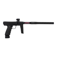
Before removing the grip frame, the bolt assembly must be
removed from the Shocker
®
CVO. Use a 1/8-inch hex key to
remove the front and rear grip frame screws [FIG. 26A]. Gently
slide the grip frame away from the receiver. A small metal mesh
lter screen (FLT006) sits inside the grip frame’s air outlet just
behind the pushbutton safety [FIG. 26B]. Take care not to drop
or lose this lter, it is necessary to trap ne dust that could
cause the pilot valve to stick or leak. If the lter is lost, obtain a
replacement as soon as possible.
REASSEMBLY Reassembling the grip frame to the body is a
reverse of the removal process. Make sure the air lter is in the
grip frame and clean and inspect the gas-though seal [FIG.27],
lightly lubricating it with GR33SE
TM
. Make certain the short arm
of the QEV pin [FIG. 31C] is on the right side of the marker, facing
forward so that it will line up with its slot in the grip frame.
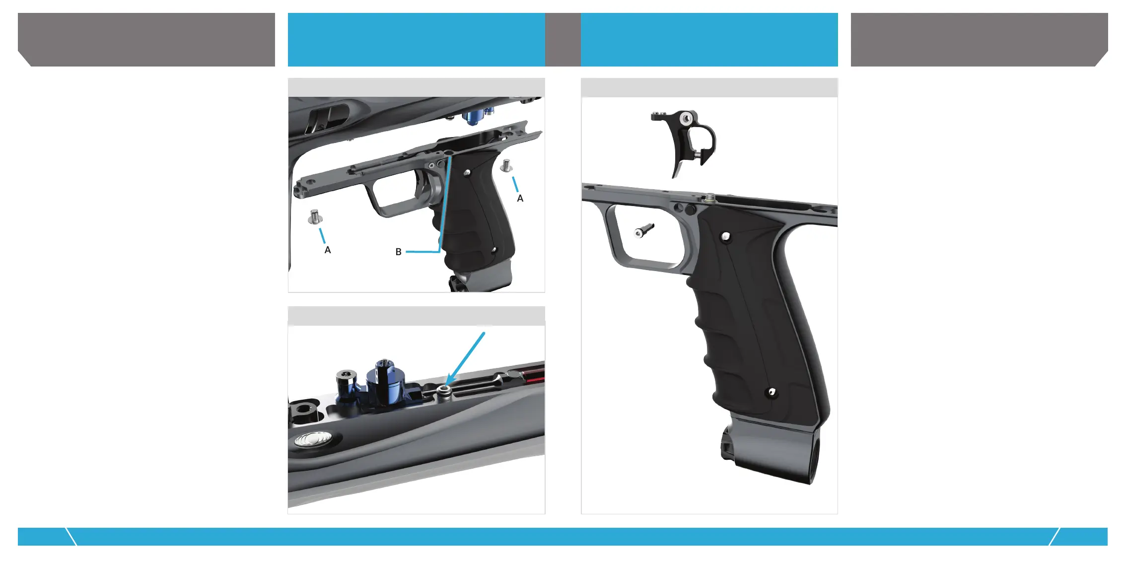
TRIGGER
TRIGGER The Shocker
®
CVO pivots on a pair of bearing sets
nested onto a low friction pin. The grip frame will need to be
removed from the body in order to provide access for trigger
removal. Using a 1/16-inch hex wrench, unscrew and remove the
trigger pivot pin [FIG. 28] and the trigger may be removed from
the top of the grip by pivoting it around the safety while sliding
it up and out.
26
GRIP FRAME
TRIGGER
28
27
GAS-THRU SEAL
B
A
A
 Loading...