22
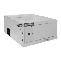
Step 9: B & C Series Unit Retrofits
For retrofitting an ESP-J series unit to an existing ESP-
B or C series, some modifications will need to be made
to the current system. The necessary changes are
below and the extent of the changes is dependent upon
the model of the unit. (Refer to Figures 2.38 / 2.39 / 2.40)
ESP-2430 Retrofits
The 7" duct can still be utilized with a transition kit (Part No.
BM-6918) available from SpacePak. This kit will reduce the
main plenum from 9" to 7" to adapt to the existing 7" duct.
ESP-3642/4860 Retrofits
The existing plenum duct, which is typically 7", will need
to be replaced with 8" X 8" duct board or field supplied 9"
round duct. The return duct and return grille will also have
to be replaced with the proper parts for the replacement
model. The reason for this change is the amount of air
supplied by current models is 30% higher than the B & C
Series models. The existing 7" duct work will reduce the air
flow and cause excessive static pressures resulting in lack
of performance and could possibly freeze up the coil which
will result in compressor failure due to short cycling.
NOTICE FOR ALL RETROFITS
It may be necessary to add outlets to the system. The
number of additional outlets will be dependent upon the
external static pressure which should be measured with a
manometer. This measurement should be between 1.2-
1.3" WC. For more details on this test procedure and
location for the test, refer to the System Start Up and
Adjustment section in this installation manual.
FIGURE 2.38: STRAIGHT DUCT OR SHOTGUN LAYOUT
SpacePak Air
Handler
9” RND w/40% of Total Outlets
7” RND w/60% of Total Outlets
A
C
D
A: No outlets in the rst 18” of straight pipe coming o the Air Handler
B: Minimum distance between outlets is 6” on center
C: Minimum distance when placing an outlet from end cap is 12”
D: NEVER place an outlet in the End Cap
B
DESIGN RULES FOR RETRO-
FITTING “B&C” SERIES SPACEPAK
EQUIPMENT TO NEWER
(D,E,F,G,J ) SERIES EQUIPMENT
ROOM
TERMINATOR
WINTER
SUPPLY
SHUT-OFF
FIGURE 2.37: WINTER SUPPLY SHUT-OFF
Winter Supply Shut-Off Installation
Simply insert winter supply shut-offs into the room
terminator openings (see Figure 2.37). Wrap the return
air filter in a plastic bag and reinstall it to block the return
air opening. Winter supply shut-offs prevent moisture
from collecting in ductwork during winter months. Be
sure to remove the plastic bag and all winter supply
shut-offs before operating the system.
FIGURE 2.36: TYPICAL CLOSET/UTILITY ROOM
INSTALLATION
FIGURE 2.35: RETURN AIR BOX INSTALLATION
 Loading...