Do you have a question about the Space-Ray LTS Series and is the answer not in the manual?
This document provides comprehensive installation and operation instructions for Space-Ray infrared radiant tube heaters, designed for non-residential spaces where flammable gases or vapors are not generally present. The manual emphasizes safety, proper installation, and maintenance to ensure efficient and reliable operation of the heating system.
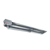
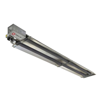
The Space-Ray infrared radiant tube heater is a self-contained unit designed to provide warmth in various non-residential environments. Unlike forced-air systems that heat the air directly, these radiant heaters emit infrared energy that warms objects and surfaces, which then re-radiate heat to the surrounding space. This method offers efficient and comfortable heating, particularly in large or high-ceilinged areas where traditional convection heating might be less effective. The heaters are available in two main series, LTS and LTU, with various models offering different heat outputs and configurations to suit diverse application needs.
The core function of the heater involves a burner that ignites gas within a sealed tube. As the hot combustion products travel through the tube, the tube itself heats up and emits infrared radiation. A reflector positioned above the tube directs this radiant heat downwards into the occupied space. A draft inducer assembly ensures proper airflow for combustion and expels exhaust gases. The system incorporates a control box that manages the ignition sequence, gas flow, and safety features.
These heaters can be installed in either vented or unvented modes. In the unvented mode, the products of combustion are expelled into the building, requiring adequate ventilation to dilute these products. For vented applications, the exhaust gases are directed outside the building through a flue pipe system. The manual details specific requirements for both venting methods, including pipe materials, clearances, and termination points, to ensure safe and compliant operation.
The heaters are particularly suitable for spaces like warehouses, manufacturing facilities, garages, and aircraft hangars. For specialized installations such as aircraft hangars and public garages, strict clearance requirements are outlined to prevent property damage or injury. The design allows for various mounting configurations, including horizontal and inclined positions, and can accommodate straight tube, L-shape, U-shape, or Z-shape layouts to optimize heat distribution and fit within the building's structure.
The Space-Ray infrared radiant tube heaters offer several usage features designed for flexibility and ease of operation. The system is controlled by a thermostat, allowing users to set the desired temperature for the heated space. The ignition system is a direct spark type, which initiates combustion after a brief prepurge period to ensure safe lighting. Indicator lights on the control box provide visual feedback on the heater's status, such as "green light ON" for thermostat call for heat, "red light ON" for diaphragm air switch activation, and "amber light ON" for spark ignition and valve opening.
The modular design of the heater allows for various configurations, including different body section lengths (e.g., 5 ft, 10 ft, 15 ft) and optional accessories like 90° elbows and corner reflectors. This modularity enables installers to customize the heater layout to fit specific building dimensions and heating requirements. For instance, U-tube configurations are recommended for spot or area heating, while straight tubes might be used for linear heating applications.
The manual provides detailed instructions for joining body sections using tube couplings and securing reflectors with speed clips. These components are designed to allow for natural expansion and contraction of the heater tubes during operation, preventing stress on the system. The draft inducer assembly can be mounted in multiple positions (vertical, 45°, or horizontal) to accommodate different flue venting configurations, with the junction box always remaining horizontal.
For optimal performance and safety, the manual specifies minimum mounting heights and clearances to combustibles, which must be strictly observed. These clearances are critical to prevent radiant heat from damaging stored materials or building components. In areas where combustible materials might be stacked below the heater, installers are required to post signs indicating the maximum permissible stacking height.
The heater's electrical connections are designed to conform to national and local electrical codes, ensuring safe power supply and grounding. The system requires a permanently live electrical circuit, controlled by an approved fused disconnect switch located near the heater. Gas connections also adhere to national and local fuel gas codes, with specific instructions for pipe joint compounds, flexible connectors, and pressure testing.
Regular maintenance is crucial for the longevity, efficiency, and safe operation of Space-Ray infrared radiant tube heaters. The manual outlines an annual cleaning and service schedule, recommending that these tasks be performed before each heating season or whenever excessive dust and dirt accumulation is observed.
Key maintenance tasks include:
The manual also emphasizes the importance of maintaining minimum clearances to combustibles, which are posted on the control box, and recommends posting signs specifying maximum permissible stacking heights in storage areas to enhance visibility and safety. These maintenance practices are designed to ensure the heater operates safely, efficiently, and reliably throughout its lifespan.
| Category | Infrared Tube Heater |
|---|---|
| Fuel Type | Natural Gas or Propane |
| Ignition | Direct Spark Ignition |
| Series | LTS |
| Applications | Commercial and Industrial Spaces |