EasyManua.ls Logo

SPALDING In-ground Basketball System User Manual

SPALDING In-ground Basketball System
21 pages
To Next Page IconTo Next Page
Page #1 background imageLoading...
Page #1 background image
1
10/18 ID# M866047
In-Ground Basketball System Owners Manual
Toll-Free Customer Service Number for U.S: 1-800-558-5234 Australia: 1300 367 582
Spalding Internet Address: http://www.spalding.com www.spalding.com.au
Write Model Number
From Box Here:
WARNING!
READ AND UNDERSTAND
OPERATOR’S MANUAL
BEFORE USING THIS UNIT.
FAILURE TO FOLLOW
OPERATING INSTRUCTIONS
COULD RESULT IN INJURY
OR DAMAGE TO PROPERTY.
Para la última información de garantía del sistema de baloncesto
Por favor visite el sitio web de Spalding Basketball en www.Splading.com
Póngase en contacto con servicio al cliente de Spalding en teléfono # 1-800-558-5234
Système de basket-ball dans le sol
Propriétaires Manuel garantie
WARNING!
PLEASE ENSURE
that (4) steel spacers
are in place between
Board Frame and Rim
Prior to tightening bolts.
(SEE PAGE 16)
FAILURE TO FOLLOW OPERATING
INSTRUCTIONS COULD RESULT IN
INJURY OR DAMAGE TO PROPERTY.
© COPYRIGHT 2018 by Russell Brands, LLC
Question and Answer IconNeed help?

Do you have a question about the SPALDING In-ground Basketball System and is the answer not in the manual?

SPALDING In-ground Basketball System Specifications

General IconGeneral
Pole MaterialSteel
Height AdjustmentYes
Installation TypeIn-ground
Adjustment Range7.5 feet to 10 feet
Rim TypeBreakaway
Rim Size18 inches

Summary

Introduction and Safety

Key Safety Warnings and Instructions

Essential safety warnings, assembly prerequisites, and model number instructions.

Safety Instructions and Preparation

Detailed Safety Instructions

Comprehensive safety rules for system operation and assembly.

Required Tools and Materials

List of essential tools and materials for installation.

Warranty Information

Basketball System Warranty Details

Information concerning the warranty for the basketball system.

Parts List

System Component Identification

An itemized list of all components included with the system.

Hardware Identifier: Bolts and Screws

Visual Guide to Bolts and Screws

Visual identification guide for all bolts and screws used in assembly.

Hardware Identifier: Nuts, Washers, and Spacers

Visual Guide to Nuts, Washers, and Spacers

Visual identification guide for nuts, washers, and spacers.

Hardware Identifier: Other Components

Visual Guide to Miscellaneous Hardware

Visual identification guide for miscellaneous hardware components.

Installation: Ground Preparation

Digging the Pole Hole

Ensuring a level ground and digging the pole hole.

Installation: Anchor Plate Assembly

Installing Anchor Plate Bolts and Nuts

Securing mounting bolts and nuts to the ground tube.

Installation: Concrete and Rebar

Concrete Pouring and Drainage

Filling the hole with concrete and creating a drainage hill.

Inserting Rebar

Procedure for inserting rebar through the ground tube assembly.

Installation: Base Setting and Curing

Positioning and Leveling the Base

Inserting and leveling the mounting plate on the drainage hill.

Concrete Curing Requirements

Advising on the minimum 72-hour curing time for concrete.

Installation: Attaching Pole to Base

Positioning Pole on Mounting Plate

Resting the pole top and aligning holes with the mounting plate.

Securing Pole with Bolt and Nut

Inserting bolt (28) and securing it with nut (22).

Installation: Lifting and Securing Pole

Lifting and Positioning the Pole

Procedure for lifting and positioning the pole with multiple people.

Installing Threaded Assembly Rod

Positioning and locking the threaded assembly rod with pins.

Installation: Attaching Yokes

Attaching Upper and Lower Yokes

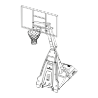
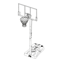
Attaching the upper and lower yokes to the main pole.

Installation: Elevator Mechanism

Connecting Elevator Adjustment to Yoke

Attaching the elevator adjustment component to the lower yoke.

Installation: Elevator Bracket Attachment

Attaching Elevator Adjustment to Bracket

Connecting the elevator adjustment to the pole bracket.

Installation: Backboard Attachment

Securing Backboard to Yokes

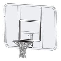
Attaching the backboard to the upper and lower yokes.

Special Instructions: Glass Backboard Setup

Foam Pad and Spacer Placement for Glass

Ensuring correct placement of foam pad and steel spacers on glass backboards.

Installation: Rim Assembly

Preparation for Rim Assembly

Tightening nut (26) and notes for board types before rim attachment.

Attaching the Rim Assembly

Steps for attaching the rim assembly to the backboard.

Installation: Height Indicators

Applying and Attaching Height Indicators

Applying labels and attaching height indicators to the yokes.

Installation: Net Installation

Attaching the Net to the Rim

Procedure for securely attaching the net to the rim.

Installation: Final Pole Securing

Uprighting and Securing the Pole

Standing the pole upright and securely fastening the pole to the anchor plate.

Installation: Removing Assembly Rod

Removing the Threaded Assembly Rod

Detaching the threaded assembly rod after securing the pole.

Final Checks and Adjustments

System Leveling Check

Ensuring the pole is level in all directions and tightening nuts.

Height Adjustment Procedure

Adjusting the system height using the crank and indicator label.
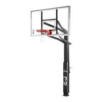
Related product manuals