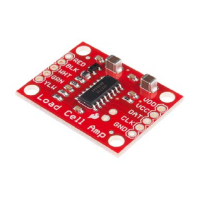
The HX711 Load Cell Amplifier accepts five wires from the load cell. These
pins are labeled with colors; RED, BLK, WHT, GRN, and YLW. These
colors correspond to the conventional color coding of load cells, where red,
black, green and white wires come from the strain gauge on the load cell
and yellow is an optional ground wire that is not hooked up to the strain
gauge but is there to ground any small outside EMI (electromagnetic
interference). Sometimes instead of a yellow wire there is a larger black
wire, foil, or loose wires to shield the signal wires to lessen EMI.
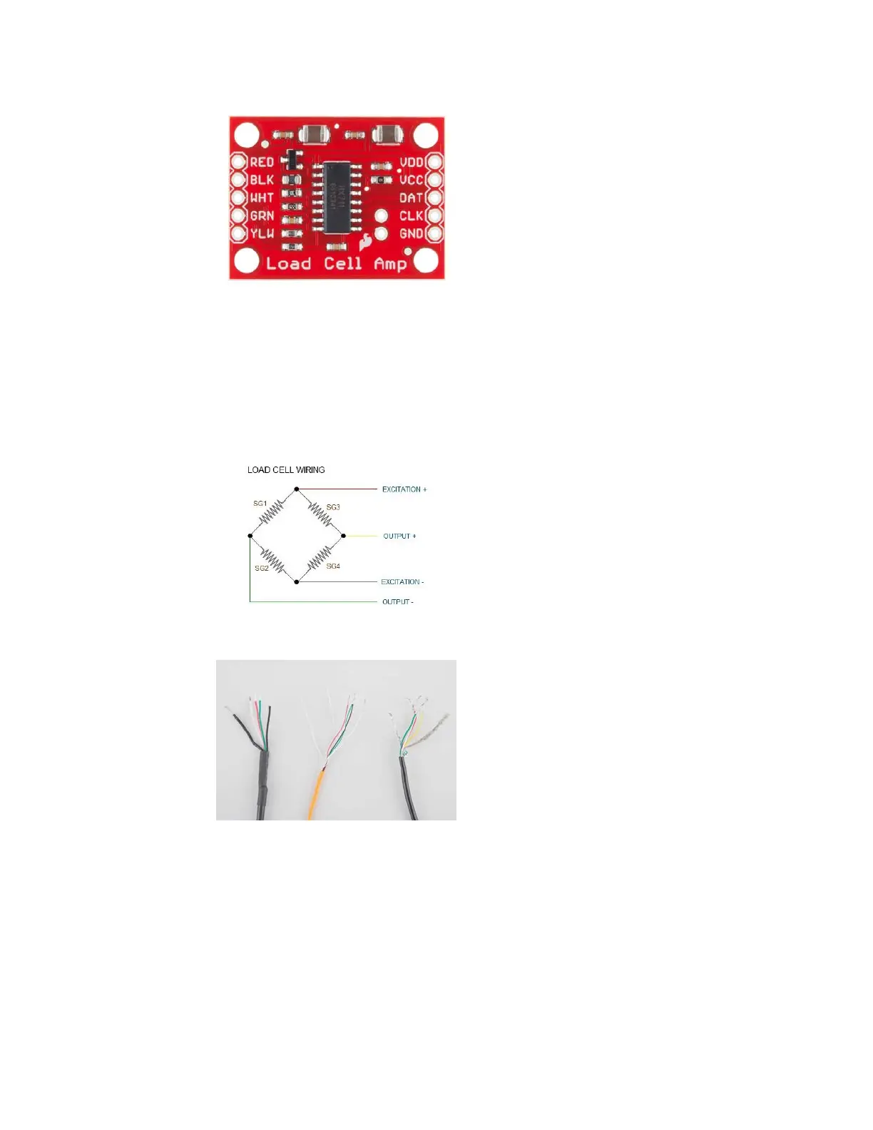
Four strain gauges (SG1 through 4) hooked up in a wheatstone bridge
formation
Here we have a large black wire, some loose wires, and foil and loose wires
respectively as EMI buffers
In General, each load cell has four strain gauges that are hooked up in a
wheatstone bridge formation as shown above.
The four wires coming out from the wheatstone bridge on the load cell are
usually:
• Excitation+ (E+) or VCC is red
• Excitation- (E-) or ground is black.
• Output+ (O+), Signal+ (S+)+ or Amplifier+ (A+) is white
• O-, S-, or A- is green or blue
Page 5 of 10
 Loading...