EasyManua.ls Logo

sparkfun Inventor's Kit - User Manual

sparkfun Inventor's Kit
26 pages
To Next Page IconTo Next Page
Loading...
Chipsmall Limited consists of a professional team with an average of over 10 year of expertise in the distribution
of electronic components. Based in Hongkong, we have already established firm and mutual-benefit business
relationships with customers from,Europe,America and south Asia,supplying obsolete and hard-to-find components
to meet their specific needs.
With the principle of “Quality Parts,Customers Priority,Honest Operation,and Considerate Service”,our business
mainly focus on the distribution of electronic components. Line cards we deal with include
Microchip,ALPS,ROHM,Xilinx,Pulse,ON,Everlight and Freescale. Main products comprise
IC,Modules,Potentiometer,IC Socket,Relay,Connector.Our parts cover such applications as commercial,industrial,
and automotives areas.
We are looking forward to setting up business relationship with you and hope to provide you with the best service
and solution. Let us make a better world for our industry!
Contact us
Tel: +86-755-8981 8866 Fax: +86-755-8427 6832
Email & Skype: info@chipsmall.com Web: www.chipsmall.com
Address: A1208, Overseas Decoration Building, #122 Zhenhua RD., Futian, Shenzhen, China
Question and Answer IconNeed help?

Do you have a question about the sparkfun Inventor's Kit and is the answer not in the manual?

sparkfun Inventor's Kit Specifications

General IconGeneral
ComponentsIncludes LEDs, resistors, buttons, and other electronic components
Power SupplyUSB
ConnectivityUSB
Programming LanguageArduino (C++)
ProjectsMultiple projects included
Skill LevelBeginner
MicrocontrollerArduino-compatible board (varies by kit version)

Summary

The RedBoard Platform

A Computer for the Physical World

Explains the SparkFun RedBoard as a development platform and a small, portable computer.

Baseplate Assembly

Anatomy of the SparkFun RedBoard

RedBoard Hardware Overview

Details specific parts of the RedBoard such as power inputs, LEDs, and pins.

The Arduino IDE

Download and Install Arduino IDE

Instructions on downloading and installing the Arduino IDE software for programming.

Install USB Drivers

Guidance on installing necessary USB drivers for the RedBoard to communicate with the computer.

Connect RedBoard to Computer

Steps for connecting the RedBoard to a computer using a USB cable.

Download and Install SIK Code

Copy SIK Guide Code to Examples Folder

Instructions for relocating the downloaded SIK code to the Arduino IDE's Examples subfolder.

Select Board and Serial Device

Select Your Board

Guidance on selecting the correct board type (Arduino/Genuino Uno) in the Arduino IDE.

Select Serial Port (Windows)

Instructions for selecting the correct serial port for Windows users.

Select Serial Port (Mac OS)

Instructions for selecting the correct serial port for Mac OS users.

Select Serial Port (Linux)

Provides a link for distribution-specific serial device setup instructions for Linux.

Circuit 1 A: Blinking an LED

New Components: LEDs and Resistors

Details Light-Emitting Diodes (LEDs) and Resistors, including their properties and function.

New Concepts: Polarity and Ohms Law

Explains component polarity and Ohm's Law (V=I*R) for circuit understanding.

Hookup Guide for Circuit 1 A

Open IDE and Upload Sketch

Code to Note: Digital Output and Delay

Troubleshooting Upload Errors

Addresses common errors when uploading code, suggesting board selection checks.

Troubleshooting Common Issues

Error Uploading Code

Troubleshoots upload errors by checking serial port selection in the Arduino IDE.

Selecting the Correct Serial Port

Guide to identifying the correct serial port by unplugging and replugging the RedBoard.

Circuit 1 B: Potentiometer

New Concepts: Analog vs. Digital Signals

Explains the difference between analog (infinite values) and digital (discrete values) signals.

Hookup Guide for Circuit 1 B

Open IDE and Upload Potentiometer Sketch

Program Overview: Potentiometer Control

Details the program steps: reading potentiometer, controlling LED blink speed.
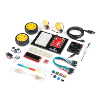