Where to Connect Speakers to the InstaLLock™ Connector (see Figures #2 & #3)
The InstaLLock™ connector has numbered locations that correspond to
the numbered switches on the front of the selector. Connect each pair of
speakers to the number you wish to use to operate that pair on the front
of the selector.
Each location on the connector is marked with a number that corre
-
sponds to the front of the selector.
There is a set of area labels provided to make identifying the location
of the speaker pairs easier. This label set includes over a hundred area
descriptions. If you wish, use a label from the set to identify the location
of that pair of speakers where they enter the connector. A separate set
of labels is provided for use on the front of the selector. (see Figure #3)
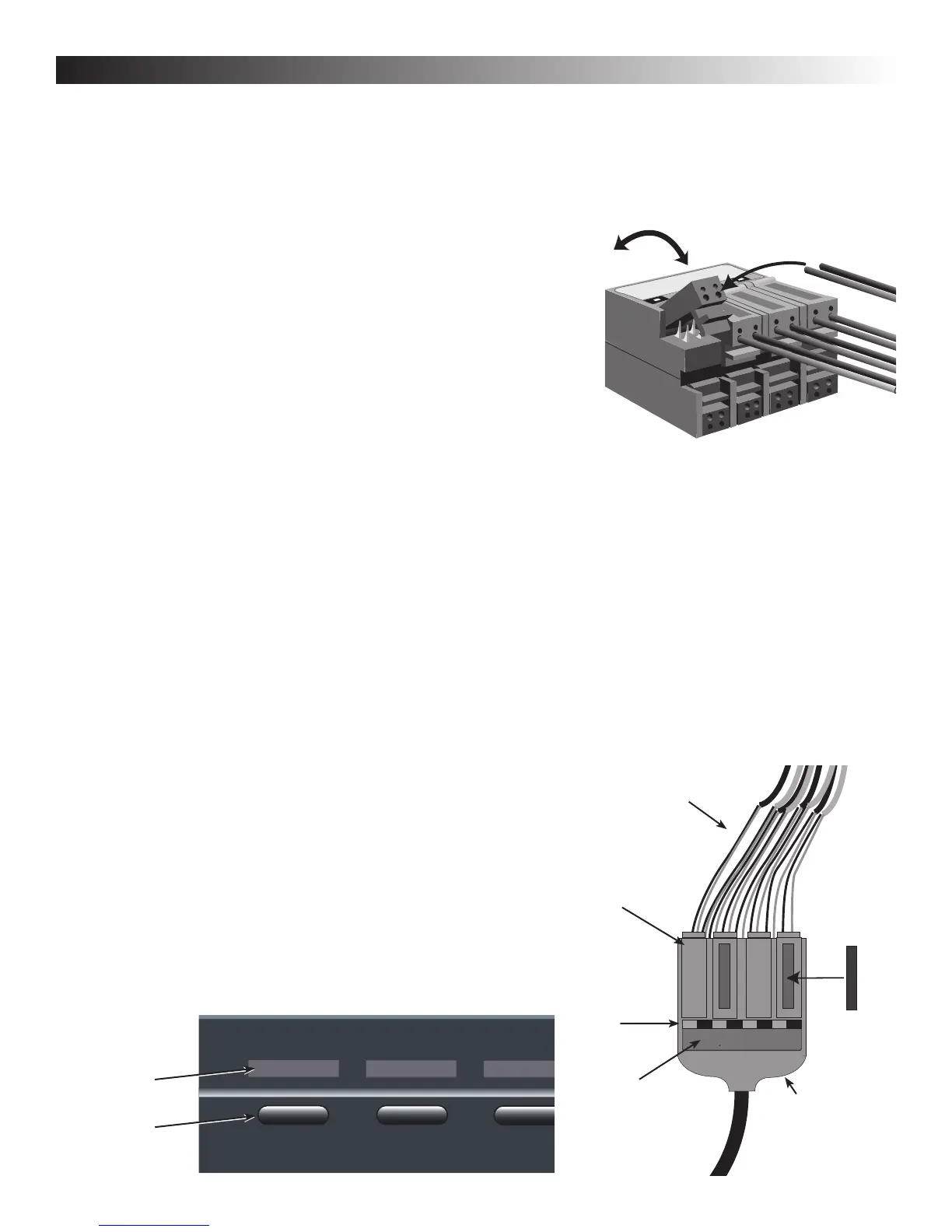
Connecting the Speaker Wires to the InstaLLock™
Connector.
(see Figures #2 & #3)
It is not necessary to strip any of the wires before installing
them into the connector. The connector pierces the insulation of
the speaker wire and then wedges itself into the strands of the
wire. This creates a "weld" that is superior to conventional termination techniques.
1) Identify the proper lever location for the wire you are inserting using the markings on the connector
For example, #1 left positive.
2) Place the appropriate wire into the smallest hole it will fit into on the lever. Slide the wire all the way into the
channel until it won't go any further. This centers the wire best over the piercing blades.
3) With both the positive and negative wire for the speaker placed into the lever, push the lever down until it locks
into place. The wire is now secure
4) Repeat the above steps until all of the speakers are attached to the connector.
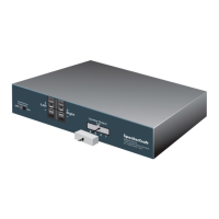
Plugging the InstaLLock™ Connector into the Speaker Selector (see Figure #1)
Once the speaker wires are connected to the InstaLLock connector the connector can be plugged into the back of
the selector at any time.
NOTE: The S8 has two harnesses, 1-4 and 5-8. Match the numbered end of the InstaLLock™ harness with the
numbered input on the speaker selector.
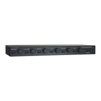
Labeling the front of the Selector and InstaLLock™ Connector.
(see Figure#3)
There are two identical sets of adhesive labels included with the speaker
selector. These labels make it easy to identify which area has been
selected when the button is depressed. One set is for use on the front
of the selector and the other is for use on the InstaLLock™ connector.
There are indentations above each button on the front of the selector.
Place the appropriate area label into each of these locations. If you can't
find the label you need you can create it by writing on one of the blank
labels using a pen or small marker.
PAGE 2 OWNERS MANUAL
LIVIN
G
RM
.
SpeakerCraft
R
--------
++++
1 2
Figure #2
Figure #3
Speaker Wires
Plug Lever
Place Area
Plug Label
In Detent
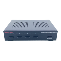
PROTECTION
S4 MULTI-ROOM SPEAKER SELECTOR
KITCHEN BATH LIVING RM DINING RM
SpeakerCraft
Number identifies
Speaker Selector
button.
Selector Label
Numbered
Area Button
Indicates +
& -- Holes In
Lever
1
2
InstaLLock™
Connector
Step #1
Lift Plug Lever
Then Push Wires
Into Hole
Step #2
Push Lever All The
Way Down Until
Flush With Top Of
Plug
 Loading...