Caution: If control is wired to a transformer, it is advisable to switch the secondary to dis-
connect power. If the primary is switched, additional snubber capacitors may have to be
added across terminals L1 and L2 to prevent power bridge damage.
Separate branch fusing or circuit breaker may be required on 208/230 VAC applications. (See
Section IV E, on page 8.)
B. Motor Armature – Wire the motor armature wires to terminals A+ and A-. Be sure the motor
voltage corresponds to the control voltage rating. See Figure 4, on page 6. Note: If motor
runs in opposite direction to what is required, turn power off and reverse armature leads.
WARNING! Do not wire a switch or relay in series with the armature leads.
Armature switching can cause catastrophic failure of motor and/or control. If
reversing or dynamic braking is required, consult the Sales Department.
C. Ground (earth) – Be sure to ground motor and control to green ground stud located between
the Bx knockouts. See Figure 7, on page 11.
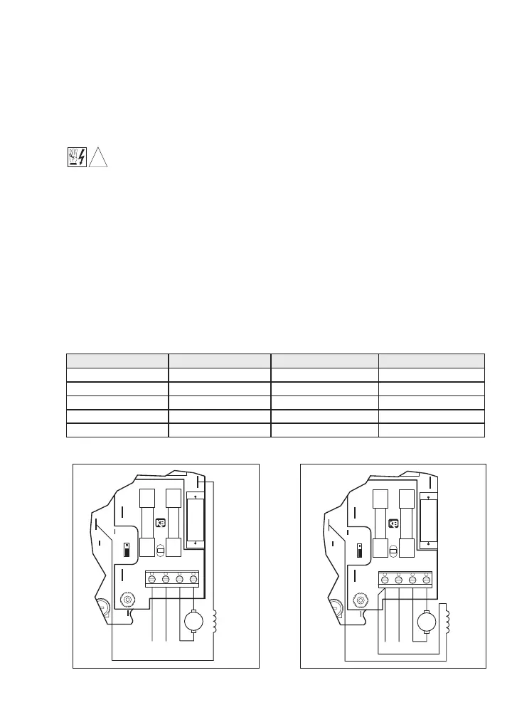
D. Field (Shunt motors only) – Do not use F+ and F- terminals for any other motor type. The
KBWM™ control is primarily designed for permanent magnet (PM) motors. However, a shunt
motor can also be controlled by wiring the shunt field directly to the 1/4” quick-disconnect ter-
minals located on the main speed control module. See Figures 5A and 5B for the F+ and F-
terminal locations. Attach motor field using insulated 1/4” Q-D female terminals. For
Standard PM (2-wire) motors, the Field is not used.
CAUTION: Shunt-wound motors may be damaged if field remains connected without motor
rotating for an extended period of time.
7
 Loading...