GETTING STARTED
SAFETY /
SPECIFICATIONS
INSTALLATION
INSTRUCTIONS
OPERATION
INSTRUCTIONS
MAINTENANCEREPAIR PARTS
2
3
Model
Max.
Inlet
Press.
Max.
temp.
Max.
Flow
Main
Ports
Gauge
Ports
Bowl
Element
Micron
Rating
Pressure
Adjustment
Range
Wt.
(lbs)
4ZK78A 250 psi 175°F 509 cfm 3/4" 1/8" Metal 40 μm 5 to 125 psi 7.00
4ZK79A 250 psi 175°F 509 cfm 1" 1/8" Metal 40 μm 5 to 125 psi 6.90
Grainger Items No. Length (In./mm) Width (In./mm) Height (In./mm)
4ZK78A 7.48/190 4.26/108 15.04/382
4ZK79A 7.48/190 4.26/108 15.04/382
• Air supply must be dry enough to avoid ice formation below +35°F.
• At 150 psi inlet pressure, set pressure of 90 psi, and a 15 psi pressure drop.
DIMENSIONS (inch)
SPECIFICATIONS
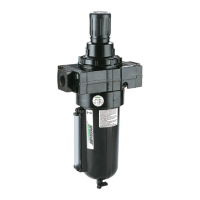
Speedaire air line filter/regulators are designed to (1) remove airborne
impurities, dirt particles, condensation and oil aerosols from compressed
air through air supply lines, and (2) adjust and maintain air pressure set
at a level which can efficiently operate air tools and other air-operated
equipments. The filter section works by means of centrifugal force and
a filter element while the regulator section is self-relieving and provides
high air flow and maintains the set pressure with minimum pressure
drop between the actual air compressor outlet pressure and the set
pressure to tools and equipments.
The device may only be operated in the permanent installation in
pressured air systems. Improper use or modifications to the device or
the use of its components which are not tested and approved by the
manufacturer may result in unforeseen damage.
Air line filter/regulators are used in a variety of air systems which may
go with air compressor, spray gun, lubricators, hoses, etc. Read and
understand all safety instructions, installation instructions and operation
instructions before using this unit. Basic safety precautions should
always be followed to reduce the risk of personal injury and/or property
damage.
GENERAL SAFETY INSTRUCTIONS
1. Read all safety instructions. Failure to do so may cause harm to you
and others.
2. Keep children and unauthorized persons away from the device.
Ensure that children are not able to play with the device.
3. Do not overload the device. Do not use the device for purposes for
which it is not intended.
4. Always make sure that the air line is in good condition.
5. Hose and connection should be inspected to avoid any leakage
before each use.
6. Residual air in the system needs to be released before service or
repair.
7. Ensure that all connections and supply lines are rated for the required
pressure and air flows.
GENERAL SAFETY INFORMATION
GETTING STARTED
SAFETY /
SPECIFICATIONS
INSTALLATION
INSTRUCTIONS
OPERATION
INSTRUCTIONS
MAINTENANCE REPAIR PARTS
1. Before installation, check whether the connections used match the maximum pressure of
the filter/regulator.
2. Shut OFF air pressure from air system. Install yoke in air line with airflow direction of
arrow, upstream of lubricator(s), and cycling valve(s) in the air line, and should be as
close as possible to the device being serviced.
3. Connect piping to proper ports using pipe thread sealant tape on male threads only. Do
not allow sealant to enter interior of unit. Contaminations in the unit may cause it to fail.
4. Position clamp ring under retainer lugs on yoke.
5. Lubricate O-ring with a light coat of O-ring grease, then place O-rings in grooves in body.
6. Make sure that arrows on yoke and body point in the same direction, then plug filter/
regulator into yoke and tighten clamp ring hand tight. Filter/regulator must be in vertical
position with drain down.
7. Make sure that all connections to the filter/regulator are tight and secure.
8. Turn bowl into body until arrowhead is in line with or to the right of the arrowhead on
body before pressurizing.
9. Install a pressure gauge to either of the gauge ports facing the operator. The other gauge
port should be plugged or can be used as an additional air outlet for regulated air.
10.The filter/regulator must be installed in such a way that no mechanical force or tension
ccurs.
INSTALLATION INSTRUCTIONS
 Loading...