Stop nuts are
provided
at the
end of the
micrometer
screw to
prevent
the
fine threads being removed
from
their
bearings.
Sometimes
these
nuts
are forced off,
and
the
micrometer
threads
are removed. When this
occurs be
careful in
replacing these
very fine threads
to see that
they are
started straight, and
that they
do
not " run."
Do not force the threads
if they
go
at
all hard. It will
help to
know
that
on most
microscopes
these threads
are left
handed. Care should also
be
taken to
see that the
little
pin
P, which
fits loosely
into the hollow
end of the micrometer
screw, is
in
position.
Should
it
be
lost it
must
be
replaced. Should
it fall into the
mechanism
it
can be
secured
only
by
removing
the nut
N at the top
of
the
arm. In some
instances
the
pin
drops
out
before
the micrometer
thread
is entirely
out of
its
trearings,
and the defect
is not noticed
until the
fine adjustment does
not re-
spond. As
stated above
remove the large
nut at the
top
of the arm
to replace the
pin.
Most
of the modeln
microscopes are of the second
class
where
the trvo
firre adjustmcnt
heads
are
one on
either side
of the
arm.
'I'he
mechanism
here is slightly
more complicated,
hence the need for the
best mechani-
cal
principles.
The bearings
for the
shaft connecting the two
heads
are on
cither
sidc
of
the arm and
should
be
in
precise
alignment
for
the
free turning of the shaft. In
no
way
is this
accomplished
as well as where the two bearings
are
in
one continuous
piece
passing
through
the arm.
Here
as
in the
other
class
the
micrometer in conjunc-
tion
with
the
lever
stands out as
superior. Here there
are a
goodly number of threads always
fully engaged
through
360"
of each thread,
insuring a steady, regular
and very durable
lateral
movement.
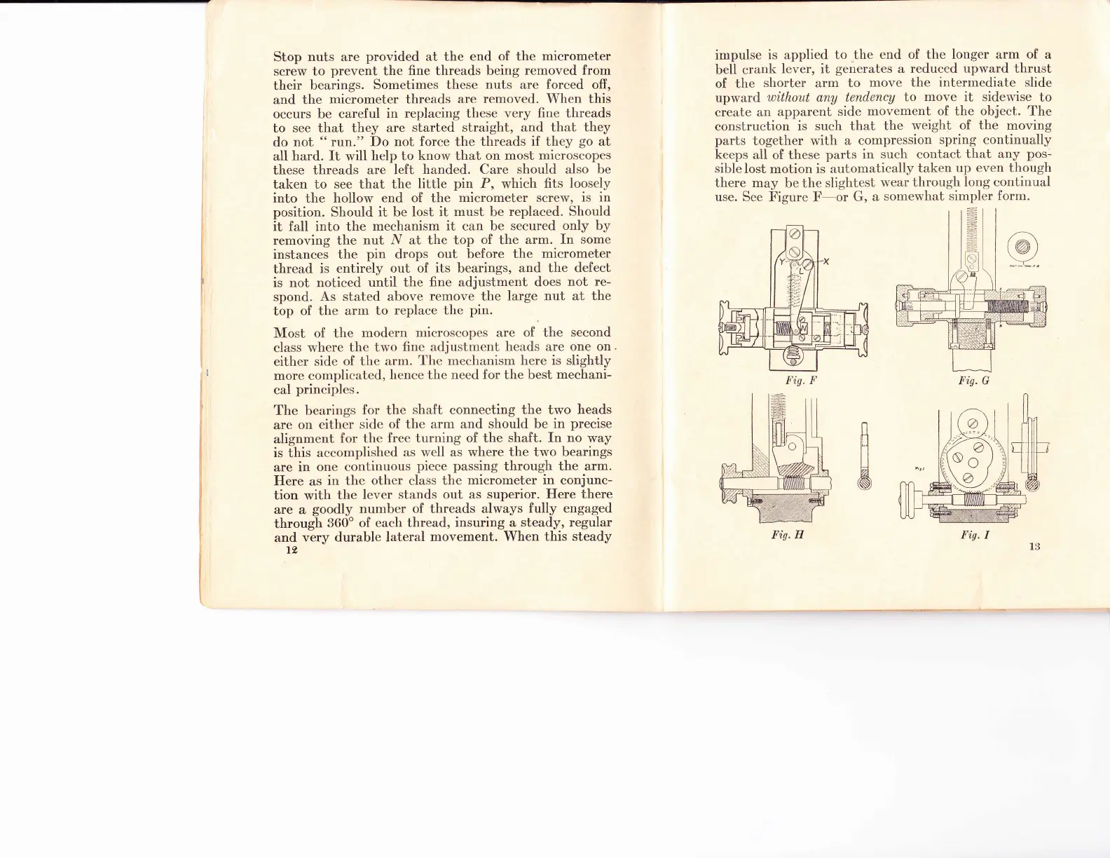
When this
steady
t2
impulse
is applied to the
end of the longer arm
of
a
bell
crank
lever, it
generates
a
reduced
upward
thrust
of the
shorter arm to
move the intermediate slide
uprvard
without
any tendency
to
move
it sidervise
to
create an
apparent side
movement of the object.
The
construction
is such that
the
weight
of the
moving
parts
together with
a compression
spring continually
keeps
all
of
these
parts
in
such contact
that any
pos-
sible
lost
motion
is automatically
taken
up even though
there may
be
the slightest
wear
through long continual
use.
See Figure F-or
G,
a
somewhat
simpler form.
B
A
Fis. F
Fig. G
Fis. H Fig.
I
 Loading...