OPERATING INSTRUCTIONS
BEFORE USE:
R
EAD ALL OPERATING INSTRUCTIONS BEFORE USE. Use extreme caution when checking
e
lectrical circuits to avoid injury due to electrical shock. Sperry Instruments assumes basic
knowledge of electricity on the part of the user and is not responsible for any injury or
damages due to improper use of this tester.
OBSERVE and follow all standard industry safety rules and local electrical codes. When
necessary call a qualified electrician to troubleshoot and repair the defective electrical circuit.
SPECIFICATIONS:
O
perating Range:
8
0-480 VAC/DC, 60 Hz; CAT III 600V
Indicators: Visual Only
Operating Environment: 32° - 104° F (0 - 32° C)
80% RH max., 50% RH above 30° C
Altitude up to 2000 meters. Indoor use.
Pollution degre
e 2. Accordance with IED-664.
C
leaning:
R
emove grease and grime with clean, dry cloth.
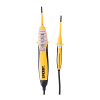
OPERATION:
To test for voltage insert test leads into outlet or carefully touch test leads to electrical
contacts or circuit to be tested. If voltage is present the neon indicators in the correct range
will glow. Use the highest illuminated range for the correct voltage. The brightness of the
bulbs will increase as the voltage increases.
To test for the live side of an electrical outlet insert one probe into the ground plug of the
outlet while inserting the other probe in the alternate sides of the outlet. The neon
indicator(s) will glow when the probe makes contact with the live side.
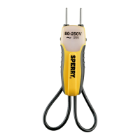
SINGLE HAND OPERATION:
Sperry’s unique design allows for convenient single hand testing of outlets when the probes
are secured side-by-side on the tester housing. Just insert the probes into the outlet and if
voltage is present the neon indicator(s) will glow.
To test for continuity just place the probe tips on the circuit to be tested.
If continuity (continuous circuit with no breaks) is present the continuity indicator LED will
light.
Batteries: This tester requires two 1.5 Volt button cell batteries (LR44, SR44, A76, G13,
AG13, GP76A, 257, D357, V13GA) for the continuity function. To test if the batteries are
good and the continuity test function is operating properly touch the two test leads together.
If the continuity indicator does not light then replace the batteries by removing the battery
cover on the back of the tester.
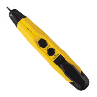
MODEL: ET6207
LONG LEAD 4-RANGE VOLTAGE-
CONTINUITY TESTER
2150 Joshua’s Path, Suite 302, Hauppauge, NY 11788
P.O. Box 9300, Smithtown, NY 11787-7929
1-888-952-1126 • 1-631-952-1126 • Fax: 1-631-434-3128
Form # 379 4/06
©2006 SPERRY INSTRUMENTS, INC.
Limited Lifetime Warranty limited solely to repair or replacement; no warranty of merchantability or
fitness for a par
ticular purpose. Pr
oduct is war
rantied to be fr
ee of defects in materials and workman-
ship for the normal life of the product. In no event shall Sperry Instruments be liable for incidental or
consequential damage.
Warning – This product does not sense potentially hazardous voltages below 80
volts. Do not use outside of the marked/rated ranges indicated.
!
CAUTION – REFER TO THIS MANUAL BEFORE USING THIS
TESTER.
Double Insulation: The tester is protected throughout by double insulation or
reinforced insulation.