EasyManua.ls Logo

Sperry Marine Rudder Angle Indicator System - User Manual

Sperry Marine Rudder Angle Indicator System
116 pages
Print Icon
To Next Page IconTo Next Page
Loading...
Northrop Grumman Sperry Marine B.V. (Representative Office)
Woltmanstr. 19 • D-20097 • Hamburg, Germany
Tel.: +49-40-299 00-0 • Fax: +49-40-299 00-146 • E-mail: service.eu@sperry.ngc.com
Operation, Installation and Service Manual
RUDDER
RUDDER
RUDDER
RUDDER
X
RUDDER
RUDDER
Rudder Angle Indicator System
05014-0128-01; 056357/B; 05 Oct 2017

Table of Contents

Question and Answer IconNeed help?

Do you have a question about the Sperry Marine Rudder Angle Indicator System and is the answer not in the manual?

Summary

Safety Instructions

Safety Notice Conventions

Explains symbols like DANGER, WARNING, CAUTION, and NOTE used in the manual.

Operator Safety Information

Cautionary Notes on Misusage and Operation

Details risks of misusage for ALR and RS-422 outputs, and operational notes.

Service Personnel Safety

Electrical Safety and Personal Injury Risks

Covers electrical shock, ESD, and risks during rudder calibration.

Chapter 1: Introduction to RAIS

System Overview and Components

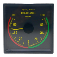
Explains RAIS system, intended use, components (RAC, RAI, RAFU), and technical data.

Design, Operation Principle, and Compliance

Covers type approval, operation logic, and regulatory conformity.

Chapter 2: System Operation

Normal Operational Mode

Describes automatic operation after power-up and configuration.

Chapter 3: Alarms System

Alarm Indication and Error Handling

Details alarm indication methods, numbers, and corrective actions.

Viewing RAC Errors via SUSI

Describes using the SUSI application to monitor current state and occurrence of alarms.

Chapter 4: Scheduled Maintenance

Maintenance Procedures and Re-calibration

Outlines visual checks, cable inspection, and re-calibration using SUSI.

Chapter 5: System Installation

Mechanical and Electrical Installation Guidelines

Covers mounting, wiring, and critical electrical safety precautions.

Feedback Unit Potentiometer Safety

Warns about risks of connecting in parallel and potential damage.

Chapter 6: System Configuration

Initial Configuration with SUSI

Details PC, SUSI installation, safety, and step-by-step initial setup.

System Parameter Settings

Configures Feedback Type, Serial I/O (RS-422), and Relay Setup.

Calibration Procedures and Points

Explains input/output calibration, tables, and modifying calibration points.

Input Calibration with Dummy Values

Describes calibrating input without rudder actuation using dummy signals.

Chapter 7: Troubleshooting

General Troubleshooting and PCB Components

Basic checks, safety, PCB layout, terminals, and LEDs for diagnosing issues.

Diagnostic LED Indicators

Lists and explains the function of various diagnostic LEDs on the PCB.

Chapter 8: Corrective Maintenance

Updating RAC Firmware via SUSI

Details the process of updating firmware using the SUSI application safely.

Replacing Alarm Output Relays

Explains how to replace failed alarm output relays (K1, K2).

Appendix

Supporting Documents and Drawings

Lists configuration tables, external docs, and system drawings.

Sperry Marine Rudder Angle Indicator System Specifications

General IconGeneral
BrandSperry Marine
ModelRudder Angle Indicator System
CategoryTouch Panel
LanguageEnglish