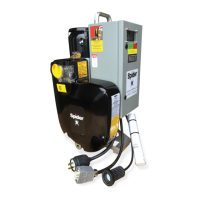
Overspeed Reset
Knob
Power Indicator Light
Primary Wire Rope
Insertion Point
Overspeed Brake
Test Button
Plug
Operating Instructions
Manual and Schematic
Carrying Handle
Sounder Power Supply Cable
Remote Receptacle
Controlled Descent Lever
Model Designation
and Serial Number
Secondary Wire Rope
Exit Guide
Normal Operation
• For routine travel in the UP direction, push in the UP operation button on remote pendant (not shown).
• For routine travel in the DOWN direction, push in the DOWN operation button on remote pendant (not shown).
• Both buttons are spring-loaded and will return to the OFF position AND apply the brake when released.
• Ifthehoistdoesnotimmediatelystop,presstheemergencystop ontheremoteANDtheoverspeedbraketest
button.
• Perform daily testing and inspection (see over) to ensure safe and correct operation. Do NOT use the hoist for
lifting until it has successfully completed the daily tests.
Reeving
• Push the primary suspension wire rope through the primary
suspension wire rope insertion point approximately
15 inches.
• Operate the hoist in the UP direction while pushing the rope
into the hoist.
• Ensure the wire rope runs freely through the wire rope exit
guide.
• Push the secondary suspension wire rope through the
secondary suspension wire rope insertion point until it exits
the hoist.
• Attach a 25 lb (11.5 kg) weight to the end of the secondary
wire rope to assist secondary wire rope travel.
Attach hoist to stirrup bar
Primary Suspension
Wire Rope Insertion
Point
Secondary Suspension
Wire Rope Insertion
Point
Wire Rope Insertion Point for
Secondary Wire Rope
721848-1/A
Hoist Operation Quick Reference
Spider SC1500 1-Phase Otis Part No. 709547-2
READ THE OPERATIONS MANUAL BEFORE USING THIS QUICK REFERENCE
Primary Wire Rope Exit
Overspeed Brake Red
Light Indicator
Stability Support/Carrying Handles