EasyManua.ls Logo

Spike Systems PBG Series User Manual

Spike Systems PBG Series
94 pages
To Next Page IconTo Next Page
Page #1 background imageLoading...
Page #1 background image
Spike&Systems:&PBG&System&Fam ily &In s ta lla ti on &
!
!
!
!
!
!
!
!
!
!
!
PBG$100/120/140/160+
SYSTEM+MANUAL+
Automated+Motorized+Hydraulic+Traffic+Controller+
!
Spike+Systems+
3623!S.!Seventh!Street!
Phoenix,!Arizona!85040!
Phone:&(602)&243=0291&
Fax:&(602)&243=0294&
!
!

Table of Contents

Question and Answer IconNeed help?

Do you have a question about the Spike Systems PBG Series and is the answer not in the manual?

Spike Systems PBG Series Specifications

General IconGeneral
BrandSpike Systems
ModelPBG Series
CategoryControl Systems
LanguageEnglish

Summary

Section 1 - Pre-Installation Planning

Warnings and Notices

Crucial safety warnings and operational notices for installation and use.

Product Models and Specifications

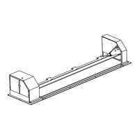
Details on PBG models, clear widths, and general specifications.

Configuration Options and Layouts

Various configuration options and sample layouts for the PBG family.

Section 2 – Physical Installation

Preparation and Unpacking

Steps for preparing the installation site and unpacking system components.

Pre-Installation Checks

Ensuring conduits are ready and preparing for loop detectors.

Plate and Cabinet Placement

Positioning the plate and control cabinets for installation.

Section 3 – Hydraulic, Electrical, and Control Installation

Hydraulic Hose and Anchor Installation

Connecting hydraulic hoses and installing concrete anchors.

Electrical Connections and Signal Wiring

AC power, traffic signal mounting, and remote switch wiring.

Electrical Reference Information

Reference information for electrical components and wiring diagrams.

Section 4 - System Operation and Maintenance

Manual Operation and Emergency Procedures

Operating the gate manually and emergency lowering procedures.

Hydraulic Pump Information and Maintenance

Hydraulic pump information, maintenance, and repair tasks.

Maintenance Reference and Troubleshooting

Reference tables for I/O, terminal assignments, and troubleshooting.

Appendix B – Inductive Loop Detector Installation

Loop Detector Guidelines and Relay Connection

Guidelines for cutting loops and connecting detector relays.

Appendix C - General Safety

Safety Considerations and Signs

General safety instructions and illustrations of available safety signs.