To Install
(XAS-SMNT, XAS..../HP or
XAS..../HS)
(XAS model only)
•
Pass the 3 machine screws M5, 85mm long
through the body (if assembling an XAS-SMNT
the unit is reversible and pre-assembled products
can be changed from Port to Starboard. Fasten
the base fairing to the clutch using the 2
countersunk screws)
•
Plan layout of deck before marking out holes for
installing the clutch with the handle opening
away from the winch
•
Ensure deck has adequate strength
•
Drill the 3 Ø5.5mm holes (Ø9/16”) through the
deck (see dimensions below)
•
Use some silicone sealant around the fasteners to
ensure a good seal and then bolt the clutch down
To replace Handle
(XAS-HDL)
(XAS model only)
•
Carefully remove handle pivot pin with suitable
punch
•
Lift handle and remove from cam
•
With new handle upright, locate in cam and
rotate to closed position. Check handle is
engaged with cam and the spring is mounted
on springarm. The springarm must be
through blue pivot in rear moulding
•
Align holes and tap pivot pin into place
•
Revolve cam slightly if necessary
To replace Handle Insert
(XAS-TAG)
(XAS model only)
•
Open handle and remove handle insert screw
•
Gently ease out the handle insert from the end
nearest handle pin
•
Locate new insert and replace screw
•
Do not overtighten
Safety Warning
This product is designed for use on sailing boats,
please consult Spinlock before using it for any other
purpose.
The sport of sailing carries a risk of personal injury.
Spinlock accept no liability whatsoever for any claim
that may relate directly or indirectly to the use of this
equipment in any manner or for any application or
loading other than advised in current product
information published by Spinlock Ltd.
General Guidance
The maximum load achievable in practice is a function
of rope diameter and construction: generally the
bigger and firmer the rope, the better the load
holding.
Service
To help ensure a long working life for every Spinlock
product we supply easily installed parts and
performance upgrades through Spinlock stockists
worldwide.
To replace Side Moulding
(XAS-SIDE)
(XAS model only)
•
A side moulding can be replaced without
removing the clutch from its mounting surface. It
is easier if the mounting screws are loosened
•
Remove three fastening screws from side
moulding
•
Remove damaged side moulding. (gently ease the
side off using a screw driver, alternatively remove
handle pin from the damaged moulding with
suitable punch)
•
Carefully replace the side mouldings and snap
together ensuring all parts are located correctly
between mouldings
•
Replace three fastening screws
•
Re-tighten mounting screws
To replace the Base
(XAS-BASE0408)
(XAS and XA models)
•
Remove clutch from mounting surface
•
Remove three fastening screws from side
of clutch
•
Remove the port side moulding. (gently ease the
panel off using a screw driver, alternatively
remove handle pin from the port moulding with
suitable punch)
•
Remove forward and rear mouldings, sliding
spring arm from the hole in the blue pivot in rear
moulding
•
Remove base from mouldings
•
Slide new base into forward and aft mouldings.
•
Push blue pivot moulding into place – from port
side of rear moulding, ensuring spring is trapped
on spring arm
•
Locate springarm in cam through hole in
port side
•
Replace side moulding ensuring all parts are
located correctly between both side mouldings
•
Replace three fastening screws
•
Replace clutch on mounting surface
To Replace the Cam
(CAM-XAS)
(XAS and XA models)
•
Remove handle pivot pin with suitable punch
•
Lift handle and remove from cam
•
Withdraw cam and springarm
•
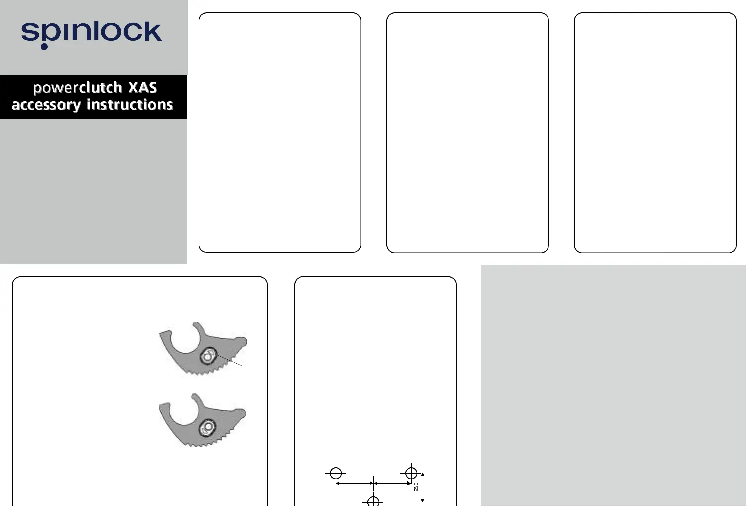
Remove springarm from the cam and insert
•
Place cam insert in new cam. Note the arrow
shaped hole in insert must point upwards
when used in an XAS assembly and downwards
when used in XA products (see Fig. 1)
•
Reassemble the spring onto springarm and into
port side of the cam
•
Place springarm and cam into body with
springarm through blue pivot in rear moulding
•
With handle upright, locate in cam and rotate to
closed position. Check handle is engaged
with cam and the spring is mounted on the
springarm
•
The springarm must be through blue pivot
in rear moulding
•
Align holes and tap handle pivot pin into place
Fig. 1
52.5
52.5
XAS Safety
Please take care to follow these important
safety rules:
•
Check that the clutch is correctly specified for
your application.
•
Check carefully that it is correctly installed
before using it for the first time under load.
•
Control release safely by checking snubbing
the rope on the winch drum.
•
Never flick open the handle when clutch is
heavily loaded, sudden release may cause
injury,
as well as damage to the rope, rig and clutch.
•
Use braided fibre rope only (never use three
strand or wire rope) Never use the clutch if
damaged.
•
Never use a clutch with damaged rope
•
Never use cleaning or lubricating solvents, or
polysulphide-based sealants : they degrade
the product.
•
Do not modify any part of the clutch.
•
Always use hand protection
published Spinlock terms and conditions.
Learn more about sailing cleats on our website.
 Loading...