www.spinlock.co.uk
Handle Assembly Replacement
Handle Assembly Replacement
28 29
Handle Assembly Replacement XX-HDLB
XX0812
how to use
pages 14-15
installation
pages 20-21
spares
pages 36-37
1. Remove the rope from the clutch.
2. For Lock Open Versions, ensure the lock open latch is in the down position.
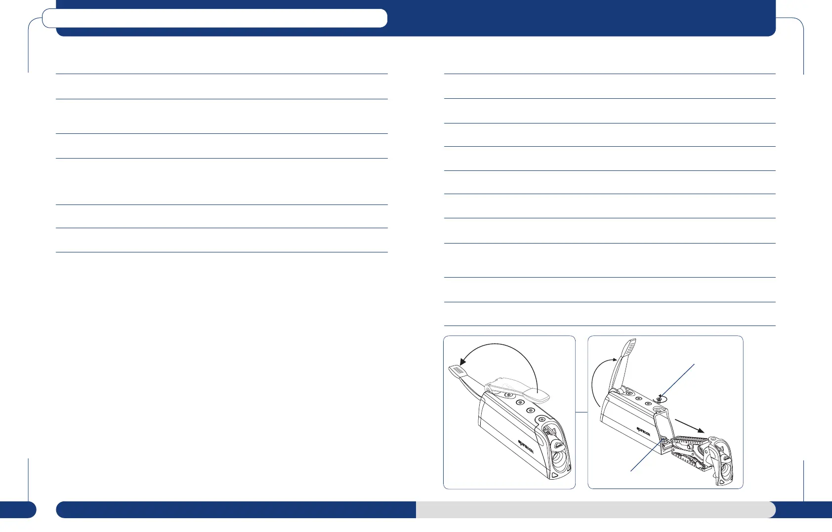
3. Lift handle and rotate fully open and then back to 90º vertical. Access to the M5 Allen screw
on the top surface that retains the rear moulding. Remove this screw.
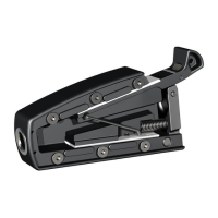
4. Hold rear cover at top, pull out from the top (See Diagram 3) pivoting around the top.
5. When the top of the moulding has rotated free of the body, lift the rear moulding to unhook
its base from the body and slide the jawset out. Excessive force is not necessary when
performing removal correctly and may damage irrepairably the jawset if used.
6. Open handle fully to remove the two M6 CSK screws on top of the product.
7. Slide out the handle assembly through the rear of the body.
8. Thoroughly clean with fresh water and inspect the following critical items:
Roller Cages (both are identical) - unclip from jaw and look for signs of wear or flats on the
roller surfaces. If flats are found replace & consider upgrade to XX-ROLL+. Ensure rollers cages are
re-attached in correct orientation (see page 26).
Jaw Bearing Surfaces - ensure that both are clean and smooth.
Jaw Grip Surfaces - clean off any rope debris. Check for excessive wear on the grip surface. If
the black anodised surface has aluminium showing through, replace with a new
XX-KIT, XXB-KIT or XXC-KIT assembly.
Jaw Linkplates - check these are attached to both sides of both jaws with pins and secured
by both pins. Ensure free movement of link plates/pins in jaws.
Release Pin - located centrally in top jaw. Check for any signs of surface wear.
Clutch Body - flush clean inside, paying particular attention to the upper and lower roller
surfaces, the two drainage runs in the base and their exits at the end mouldings.
Re-assembly
1. Re-install handle assembly.
2. For Lock Open Versions ensure the lock open latch is in the down position.
3. Lift handle and rotate fully open and then back to 90º vertical.
4. Insert jaw assembly in body of XX.
5. Angle rear moulding backward, to locate lower fixing hooks in body.
6. Rotate top of cover into place flush with XX body.
7. Insert M5 Allen screw on the top surface that retains the rear moulding. Hand tighten only.
8. If Lock Open version, ensure latch is fully operational in both up and down positions as well as
opening and closing the handle fully.
9. For standard versions, open and close the handle fully to ensure fully operational.
10. Open handle fully and thread rope through XX body.
M8 fastener
M5 Allen screw
90º