www.spinlock.co.uk
XX0812 to XX0812/L
XX0812 to XX0812/L
32 33
Converting XX clutches lock open version
XXC0812
how to use
pages 14-15
installation
pages 20-21
spares
pages 36-37
The XX0812, XXB0812 and XXC0812 can be converted to the XX0812/L, XXB0812/L
and XXC0812 /L with the purchase of the XX-LCK.
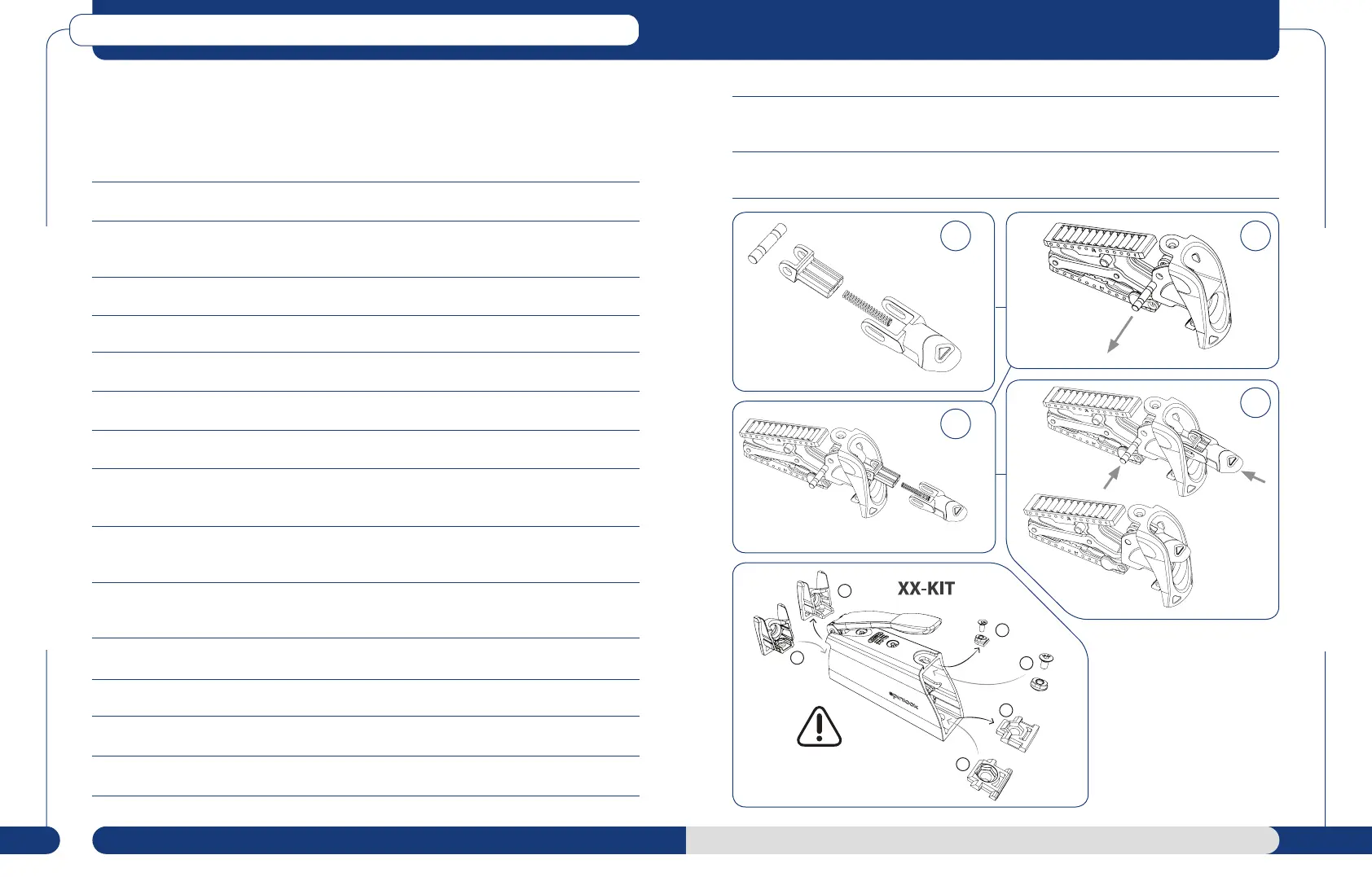
Fitting procedure:
1. Check kit components before commencing (Diagram 1).
2. Lift handle and rotate fully open and then back to 90º vertical. Access to the M5 Allen screw
on the top surface that retains the rear moulding. Remove this screw.
3. Hold rear cover at top and rotate and pull out from the top.
4. Pull the complete rear moulding and jaw assembly free from the body.
5. Remove Latch Pivot Pin (Diagram 2). (Note location of spring arms to help with No. 8).
6. Insert Latch Spring and Latch Lever Support into Latch Lever (diagram 2).
7. Assemble lock open version as per diagram 1.
8. Insert jaw spring ends into latch lever support, so that the spring coils align with holes in
latch support.
9. Push Latch Lever and Lever Support together and locate with Rear Cover to allow all
holes to align.
10. Push pin through holes in Rear Cover, Latch Lever, Latch Support and Spring Coils.
An audible ‘Click’ will be heard (Diagram 4).
11. Insert jaw assembly into body.
12. Angle rear moulding backward, to locate lower fixing hooks in body.
13. Rotate top of cover into place, flush with body.
14. Insert M5 Allen screw on the top surface that retains the rear moulding. Hand tighten only.
15. Ensure lock open latch is fully operational in both up and down positions as well as opening
and closing the handle fully.
16. Put latch into ‘Up’ position and thread rope through body.
3
1
4
2
7
3
7
7
3
3