IM-P402-37 AB Issue 9 7
4. Installation
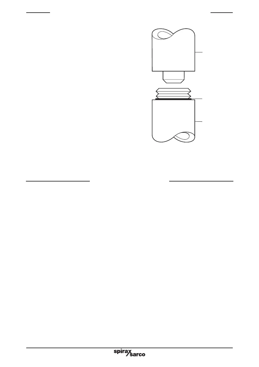
The probe consists of a metal rod
completely insulated from the liquid by
PTFE sheathing. It works by sensing the
variation in capacitance caused by a
change in water level, an increasing level
giving a proportionally increasing output.
The capacitance is measured by the
preamplifier and transmitted as a dc signal
to the controller or transmitter. Control and
switching levels are set in the controller.
The preamplifier sensitivity is selected
according to the immersed length of
the probe, and the wiring variations
that achieve this are described in the
preamplifier Installation and Maintenance
Instructions (IMI).
CAUTION: Over-tightening by hand or
use of a wrench will cause damage
to the 'O' ring and may damage the
preamplifier.
PA20
'O' ring
LP20
Capacitance
level probe
Fig. 2
WARNING: The LP20 probe must not be cut to length. Do not install the probe
outdoors without additional weather protection. Do not block the drain or the
vent holes.
A protection tube of 80 mm (3") nominal bore is required for boilers, or in tanks where
turbulence is likely. This should be as long as possible, and at least long enough to
cope with the expansion of the probe at maximum operating temperature (0 - 239°C,
32 - 462°F). Allow 20 mm (¾") clearance for probes up to 750 mm in length, and 38 mm
(1½" for longer probes).
4.1 Install the probs as follows
- Ensure both male and female threads are in good condition.
- Use up to three turns (no more) of PTFE thread sealing tape on the probe thread.
WARNINGS: Do not use excessive tape. Do not use paste type jointing compound.
- Fit and tighten the probe by hand initially - use a suitable spanner to tighten the probe.
Under no circumstances use a pipe wrench.
- Due to the nature of a taper / parallel joint it is not possible to recommend tightening
torque figures.
- Do not overtighten - there should always be visible thread on the probe.
- Note: The probe thread will not 'bottom out' (i.e. probe body hexagon contacts the
face of the female screwed connection), unless there is excessive wear or an
out-of-tolerance female thread, in which case it will be necessary to replace or re-work
the flange or connection. After installation ensure that resistance from the probe body
to the pipework / boiler shell is less than 1W.
3. How the LP20 probe works